
PAGE UPDATED Original website is alas down😐
But a copy was still available at the ARCHIVE
https://web.archive.org/web/20200315114537/http://members.chello.nl/e.stroetinga/Didcot.htm
This is a model on 5" gauge of a Great Western Railway, 14xx 0-4-2 class steam locomotive. The model was started in 1996 and finished in 2007.
This is a model on 5" gauge of a Great Western Railway, 14xx 0-4-2 class steam locomotive. The model was started in 1996 and finished in 2007.
    Here a view of the cab, while groundlevel driving at PTVF in Brussel, october 2015   At speed at the track of "Stormpolder" (Rotterdam) in june 2005 Part I  The real loco 1420 and train at Riverford Bridge (England). This is one of the few survivors of the Great Western Railway 14xx class 0-4-2 tank locomotives (1420, 1442,1450, 1466 are preserved). Introduced by C.B. Collet in 1932 to replace the ageing 517 class tanks, of which the 14xx were updated versions. They were originally numbered in the 48xx series and were fitted for working auto trains. Mainly for use on branch lines, they were also capable of a fair turn of speed. I chose this locomotive for my next project because I saw it in a movie "The Titfield Tunderbold" and liked the appearance of these tiny engines. I started out with the 7 1/4" gauge version 'Dart', designed by Martin Evans and serialised in ME, but I found it was too big to handle and to make with my workshop equipment. So I ordered the catalogue of Reeves (England) and found there was also a 5" gauge version.  I started with the model locomotive in January 1996, after buying the drawings (RV 70 'Didcot') and the wheel castings from Reeves. The design for 5" gauge is from H.N. Evans, and although the copy isn't very good (sometimes hard to read), the drawing is fairly good, with lots of general detail. With the aid of a set of original Swindon work drawings, I should be able to make a close copy of the real thing in the 1" scale.  The wheel casting of one of the driver/coupled wheels as they came from Reeves (England). Posting and packing costs are very expensive, so I try to minimise the use of castings. Alas the bosses are to big (according to the prototype), but that is hard to alter now. The cast iron of the wheels is of a good quality and easy to machine.  Milling the horn blocks in the frames. My old (1948) American Van Norman no.6 milling machine is put to use for milling the horn block castings. The blocks are riveted in the frames with 2 mm steel rivets. Not original GWR, but very sturdy. To prevent oil from getting between the horn blocks and the frame (which is very inconvenient during painting) the horns were first fixed with glue (Loctite), but a thick coat of wet paint before assembly will also do.  The cutting of three groves with a saw cutter for the horn cheeks of the trailing axle. A small piece of scrap metal was used to make a fixture for holding the cheeks (brass angle) in the correct position during cutting the slots. In these slots some small webs were inserted and soldered. Only two small tool clamps were used to actually hold them down during the milling process. The large saw cutter was used at a slow speed. 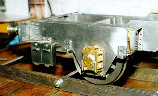 The trailing frame of the little 0-4-2 engine. The horn cheeks and axle boxes were built up from brass. Aluminium-bronze bearing bushes are glued in to the axle boxes. I still have to solve the problem how to make the working leaf springs. The two small boxes on the rear are battery boxes, which were used (on the prototype) to power the ATC (=Automatic Train Control).  Shaping the block for making the smokebox saddle. It takes up some time, but it's nice to watch the shaping machine at work and it is of course capable of taking large cuts at a time. Usually I use some suitable scrap metal for making these parts.  Boring out the smokebox saddle on the milling machine. It was first shaped from solid (again avoiding the casting, due to the high price of importing). The radius (for taking up the drum type smokebox) was also first roughly shaped in form, before turning to the boring head. This saves a lot of time, because the boring head can’t take large cuts.  Glueing the crank axle on the wheels, set at 90 degree angle. For this procedure I used ACAD to calculate the height of two pillars, which in their turn make sure that the crank pins are set at 90 degrees and (more important) that both wheel sets are exactly the same. It worked out perfectly, with no adjustments needed on the coupling rods. The set-up for glueing is made on a machine table (an old spare from a shaping machine), which ensures that the wheels (of which the flanges fall partly in the T-slot of the table) are in line and don't roll away during the setting of the glue (Araldite).  Forming the chimney on the smokebox, using a large bolt to press (and hold) it down on the smokebox. It was turned from solid steel. The bottom flange of the chimney was turned very thin (approx. 1 mm) and was ‘squeezed’ on the smokebox until most of the circumference was in contact with the smokebox drum. The bolt hold it in place, when I was beating down the last part of the flange with the aid of a steel hammer and a brass rod (about 1" in diameter). No heating up was required.  The cylinder block under construction, made from solid bronze bar. Due to high price of the cylinder set, I decided to use bronze bar instead. (At the beginning I even considered free cutting chrome steel, which I had, but by e-mail correspondence I got convinced not to use this). Most of the work was done by the shaping machine, which is able to get a smooth surface (especially for the port face). The bore (30 mm) was made on the lathe in a 4-jaw chuck. I am thinking of using O-rings for the piston rings.  Firebox plate on the former during the beating process. Two steel former plates are used to hold the plate in place in the vice, during the beating (done with a Nylon hammer). The former plates are made of 10 mm thick steel. The copper plates are 3 mm thick. I understand that for 5" gauge it will be a small boiler with an even smaller firebox. The flanges were made to length, after they were formed. In this case the blanks can be roughly cut to shape, when starting with fabrication of the plates.  The plates in a temporary fire hearth for annealing. Heating up was done by a large Sievert propane torch. The annealing was repeated three to four times, to get the final shape. The annealing itself is nothing more than heating up to bright red and let it cool down again. This softens the copper, so it won’t ‘crack’ during the forming process. The fire hearth itself is not much more than a couple of firebricks temporarily placed together.  The throat plate after forming from 3 mm thick copper plate. The ring for taking up the boiler barrel was formed first in a steel ring. A disk on the former plate (with an outside dimension, the same as the inside diameter of the ring in the copper plate) held the throat plate in position during the beating of the outer flange. With this method everything will be nicely lined up during assembly and the connection between boiler barrel and throat plate will be strong.  The model loco as it was at our 'open day' at Breda in June 1997 (the Netherlands), with an GWR 45xx class Firefly. You'll see there is still a lot of work before she will go.  Myself and the loco frame at our annual steam meeting June 1997 in Breda. Driving my 3 1/2" 'Mona' took up a great deal of the day. But there was still time to take this photo. Our Steam Society 'Stoomgroep Zuid' has a club track in Breda, next to some sport fields. It's an all steel (noisy, but charming) elevated 5"/3.5" track, with a turntable and steaming bays. Although it is a good track (266 metres long, kidney shaped, almost level) and open all year, it is alas not much used by members of our society.  Another look of the locomotive at a show in Turnhout (Belgium). Here they have a large 5" and 7 ¼" gauge ground level track trough a large part of a park.  The model locomotive as it was November 1997. The frame is on its wheels (not yet sprung) and the brake gear is partly completed. This took up much time, because the ordered brake hanger castings weren't very good. I tried to make them look better (rough casting, out of line and too large) but this wasn't satisfactory. So I've made new ones, building them up from steel plate and some bushes. The cylinders are already fixed between the frames. Due to building a home extension, there wasn't much time for model engineering in 1997. There are two ways of doing things: The wrong way or the Great Western Way Part II
Here are new photos and text of the boiler progress of the Didcot. I started with the boiler
on the first of April 1999 and it was tested on the first of November 1999. The drawing of the boiler was changed to metric and modified to suit the Dutch boiler inspector, and a ACAD14 file is available.
I presume these photo's will be helpful for new boiler builders; as I found there is not
much information about model boiler building on the internet.  The valves were milled from cast iron and I hope this give a good service on the bronze port face of the cylinder block. On my 3.5" 0-6-2- ‘Mona’ I used a cast iron port face with bronze valves and this proofed to be excellent in service. The buckles are milled from a piece of 5 mm thick brass and are on the photo still attached to each other. Such a buckle allows the valve to set it self to the port face under the steam pressure.  By this locomotive there is one combined steam chest that sits between the two cylinders. Because this is an inside cylindered locomotive there is not much space for the steam chest (if one wants to place to reasonable sized cylinders also in-between the frames). The steam chest is only 20mm wide. The valves them self are 9 mm high.  This top-view shows how the valves will sit against the port face of the cylinder. Valve setting was done this way, which give a good visibility. The valve rods were made to length, so that afterwards (when the steam chest was put in position) there was no need to set the valves again.  I would like to take the opportunity to explain how I made a 'double' flanged throat plate for my belpaire boiler of my 5" gauge 0-4-2 locomotive. Not that I think that I'm an expert on the subject (far from it), but I found it quite easy to make the 3mm thick copper throat plate using only a simple jig. This method is very simple, but you have to work the other way around as normal.
See below for the step by step explication of making the boiler parts Step one The former plate What you need is a normal former to make the throat plate (i.e. made of 10 mm steel plate) in the shape of the throat plate. The same plate can also be used for forming the back head, if your belpaire firebox is parallel, but it is smaller in size as the final throat plate . How much smaller in size? I usually reduce the size of the former plate, by reducing the size of the final throat plate (as on the drawing) by twice the thickness of the material used for the throat plate (in my case that was 3 mm copper plate, so the width was reduced by 6 mm, the height by 3) The material that is only folded over a straight line will stay 3 mm in thickness (minus a very small reduction if you hammer to hard with a steel hammer, but without reduction of thickness if you hammer with a Nylon hammer) The material in the rounded corners will gain in thickness by hammering (by clenching the material), but this extra thickness (only a few tenth of a millimetre) is afterwards easily removed by the aid of a file (which also smoothen up the surface, which makes a nice joint for silver soldering). Step two The copper material for making the throat plate Start with the round flange that will take up the boiler. There fore I used a copper plate that is big enough to cover up your former + the extra for the flanges themselves (don't forget that, and take enough for that..... in my case (10mm thick former plate) I used almost 20 mm extra material at both sides of the former (this gives you more 'play' afterwards). Indicate on this plate where the centre of the hole will be (the hole that will flanged to take up the boiler barrel) Step three The extra parts of the former Now you need two extra parts, that are quite easy to make and use, if you can get hold of the material. First you need to fabricate (a job for the lathe) a steel ring. Height of the ring only has to be 15 to 20 mm. Wall thickness of the ring has to something about 8 to 12 mm or larger. (so it will not deform during the process. I used a piece of thick walled steel tube that I had in the scrap box) This ring will have a inside diameter that is the sum of : the outside diameter of you boiler barrel + twice the thickness of you plate material used to make the throat plate of (i.e. 3mm). But because the material will be stretched you'll have a reduction in material thickness...........so 3 mm will not stay 3 mm but can become something like 2.8 or even 2.6 mm (depending on how high (deep?) the flange must be.....I use a flange height of 10mm which gave me a final thickness of 2.7 mm) But you can work very accurate here, by making the inside diameter of the ring firstly the sum of the outside diameter boiler barrel + two times 2.5 mm (if you use 3 mm thick plate). I'll explain how to use the ring in a moment, but let me tell you now, that later on you can exactly measure the material reduction, and if not ok. (probably to small when 2.5 mm used as calculation figure) you later on chuck the ring once more in your lathe and now enlarge the inside diameter of the ring to the correct value found by measuring on the job. A second part you need is a disk (steel, hardwood or any other reasonable strong material....I had a piece of Tufnol) that is about 15 to 20 mm thick and has an outside diameter that is the same (or a few millimetres bigger) than your boiler barrel. To the correct dimension I come in a moment. Step four More tools As an extra it would be handy if you had a steel disk that is about 2/3 of the diameter of the boiler barrel and about 40 to 60 mm in height and a flat strong surface (preferable a steel/hardwood plate of 10 mm or more) of a size that is big enough to take up the complete copper plate. Step five Bolt and clamps You now have almost all the parts you need to make you throat plate (which shouldn't take long to make, I did mine in one evening) The only thing you need is a bolt, (nothing fancy, dimensions I'll give later) and a couple of clamps. Step six First production step Cutting the hole. Take your copper plate and mark out the position of the hole. Centre pop it and scribe a circle that is the size of your outside boiler barrel minus twice the height of the flanges and a bit extra reduction for safety (2 to 5 mm will be good) When your at it, also scribe a circle that had the outside boiler diameter size. Cut out this hole. I used the boring head on my milling machine and made a hole of about 75 mm if I remember correctly for a 106 mm outside boiler barrel diameter. Step seven Beating the boiler flange. first stage Anneal the copper plate. Take the steel ring and put it on your work bench. Put the copper plate on top and try to align the hole with steel ring (i.e. place the hole concentric above the ring..........no great accuracy is needed, just take a good look) Now gently start beating the plate inwards the ring with a steel hammer. During this progress the plate and ring will shift a little bit, but by in-between adjusting the position not much will go wrong. Do this for the complete circumference, but do not try to beat the flange in one go. This is wrong. First stage (before annealing again) you only will be able to beat the flange in for about 20 or even 30 degrees. After annealing you can maybe go as far as 45 degrees. This is far enough. Do not go any further. Try to position the ring and hole as you go, but a little shift, or unroundness of the hole isn't important yet. Step eight Beating the boiler flange. second and last stage Anneal the copper again. Take the surface plate. Put it on your workbench. Put the annealed copper plate on it, with the flanged part facing up-wards. Put the ring over the partly formed flange and try to locate it a good as you can (by vision only should be sufficient). Now use the clamps to fix the ring on the copper and that in its turn on the surface plate on your bench. (I used a 10 mm steel plate, which I clamped on the table of my milling machine, holding the ring, copper plate and surface plate (that was needed so I would damage my table) in one go, firmly in position for the last step of forming the flange.) Once this set up is made, take the steel disk, put it inside the hole on the surface plate and start shifting it around. Use it like a hammer by sliding it on the surface plate and hitting the copper flange. This will now come up right (work on the whole circumference, not just on one spot) and will eventually touch the inside of the ring. (maybe another annealing step is needed) Because the steel disk is in contact with the surface plate, while swung around, the edges of the flange will turn out 'square up' (so a nice flange for taking up the boiler on the outside) Step nine Checking You now should have a copper (flat) plate with a flanged hole in it. This should take up the boiler barrel. If not (to small), measure the inside diameter of the copper flange, and open out the diameter of the steel ring accordingly (for instance, boiler barrel 106, but your flange turned out to be 105.6. Turn the steel ring than 0.4 mm bigger than it was) Position the whole lot once more and clamp it on your bench (after annealing) and give it another treatment with the steel disk. When done, cut the flange height to the desired dimension (i.e. 10 mm) with a file or as I did with an angle grinder. Step ten Take the disk (of step three) Chuck it in your lathe, drill a hole in the centre to take up the bolt (I did use a M6 bolt) and turn a stepped 'reversed' flange to it.(so remove material form the original diameter of a length.........don't know how to describe this in English but I hope you understand what I mean). This stepped flange will have a diameter that is the same as the outside of the boiler barrel ( so it will fit nicely in the flange) and is just as 'long' as the height of the copper flange + the thickness of your plate. (in my case this step was round 106 x 10+3 long mm. The disk was round 112 x 20 thick, with this 106 x 13 turned out............you understand??) (112? that's 106 + twice material thickness.......read on and you'll see) Step eleven (almost there) Locate hole. Locate on the made former plate (as described in step one) the centre of the boiler barrel. Drill and tap a hole there to take up your bolt. Step twelve Put the copper plate (with flanged hole) on the former. Place the disk inside the hole and bolt it to the former. Now you see why this stepped flange on the disk is important. It will locate and hold the copper plate in position and pressed down on the former during the next stage. Now put the steel ring over the flange once more. Because the disk outside diameter is 112 you'll find that the steel ring will slip over the disk nicely. Step thirteen After annealing you can now start working on the outside flange in the usual way (I presume you formed boiler plates before...... if not.......follow the words and music of LBSC in his book of the Mona.......Great locomotive by the way..... drive mine regularly) Step fourteen. During the beating process, the flange that is already formed tries to move away. In this case however care is taken for that by 'locking it up' between the disk and ring. By bolting the disk to the former, you're sure that every thing will be nicely lined up and stay in position during the final flanging process. (of course extra annealing is necessary as usual) Hope this describes the process and is of any use. The photo's show the throat plate and the formers and disks used.  These are the boiler backhead and throat plate and their formers. Clearly visible on the left is the Tufnol disk with its locating bolt, that held the throat plate on its position during the flanging of the outer shape.  The complete formed boiler parts awaiting the next stage of manufacturing.
A careful study of the drawing and design was now necessary, so the final boiler will be satisfactory. I only found later on that I still had made two mistakes! Although I used ACAD to design the boiler the boiler inspector found during his inspection of the parts that the distance between four of the fire tubes would be to small for good water circulation. He advised me to make a new firebox tube plate and arrange the fire tubes layout in such a manner, so that there was always a minimum of three millimetres of space between around each tube. So back to the computer and setting out a new tube layout. With some moving around and some puzzling this problem was solved, which took in fact more time than the fabrication of the new plate.
The second mistake was only a small one, but for me enough to correct. The top feed bush
was located on the drawing in the wrong position. On the boiler drawing the dimension and location was different than on the general arrangement, and I only spotted this problem , when I put the drilled boiler barrel on the drawing. A disk of 3 mm copper was used to cover up the wrongly located hole and a new one was drilled in this one. Now on the correct position....... only 7 mm more to front of the boiler. I wonder if anyone had noticed if I didn’t change the location, but once you’re in studying the prototype that closely, you want to make your model as good as possible. Am I becoming a rivet counter?? I must beware!!  In this position the outer- and inner-firebox will be located once the boiler is finished.
This is still the old firebox tube plate that was later replaced for a new one for the reasons stated above. The water space on the sides and back of the firebox is 8 mm (7/16”) and in front it is 10 mm (3/8”).
The inner firebox will stick out of the boiler for about 8 mm. This flange will than be
used for fixing the ash-pan to it.  The drilling and boring of the holes for the fire- and superheating tubes was
done on my milling machine. With the aid of the Digital Read Out is easy to locate the holes in the correct position, as determined with the CAD software.
The large superheater tube (25 mm) wasn’t drilled, but made with the boring head.  A test set-up of the tube bank. The holes are all a little oversized and not, as
stated in most of the available construction notes in the ME press, reamed to a close fit. This
would be incorrect for soldering, as the tubes will expand during the process and than there would be no gap for the solder the penetrate. To prevent leaks around tubes, a rough surfaced hole and a little over dimension of the hole are ideal, so that solder will always be able to get in the joint.  The circular layout of the tube bank is good visible in this picture. The one superheater
tube will be equipped with a concentric stainless steel superheater element.  The 2.5 mm thick copper plate of the outer firebox shellwas annealed first,
and than bended by hand of a wooden former. The former was made of several plates of 15 mm thick MDF plate glued together. Each plate was first CNC milled in the contour of the firebox. A former like this takes some time in preparation, but once you have it, the copper plate is ready in minutes. Working with such a former block makes sure that everything will get the correct dimension and shape.  This was the set-up for drilling and boring the dome-bush hole and top
feed hole in the boiler barrel. Alas, as described earlier, the top feed bush was in the wrong position, and had to be corrected later on.  The bronze dome bush was first turned in the lathe and in the milling
machine the 12 holes were drilled and taped, that later on will be used hold the inner dome. Four small M3 bolts were used to clamp the dome bush to a steel plate, which in its turn was clamped in the vice. In this set-up it was easy to bore out the large radius on the underside of the bush, with which the bush will sit on the boiler barrel.  Here the inner and outer boiler are standing aside. The inner boiler looks that pink, because it was sand blasted after soldering. This gave the opportunity to check if all the tubes and other joints of the fire box were good. The small mistakes that occurred (not enough silver solder in one joints between crown sheet and fire box tube plate) could now easily resoldered. Better be safe than sorrow!  The outer boiler is now also soldered and the location is set for the
hole for safety valve and the hole is made. The outer boiler is clamped to the milling
table by use of a large T-bolt going through the firebox and boiler barrel. On top a steel plate with a hole in it, was used to take up the nut. An extra clamp is used on the throat plate to prevent the boiler shell from shifting during the process.  On the Swindon work drawings I found that the fire hole was conical shaped. I wanted to copy this on the model, because I experienced on my 3.5" tank locomotive, that you do not have a good view on the fire, once you are in the driving position behind the locomotive. A conical shaped fire hole would give a far more better view on the small fire box and it would give also the opportunity to control the fire better. For this purpose a special conical ring was turned from copper bar. On the outside of the boiler backhead it is only 36 mm in diameter, but on the inside it is almost 60 mm in diameter.  The fire hole ring is hardly visible lying on top of the fire box, but the good view inside the
firebox is very clear.  Soldering was mostly done with two Sievert propane burners. The good summer we had
in 1999 allowed me to work outside the workshop. With such a large boiler (although very small for 5" gauge) it is almost impossible to solder inside. The amount of heat necessary for soldering would melt the sealing in the work shop. The small parts I did solder in the work shop raised the temperature very quickly to 45° C.
When the parts were sufficient cooled down after soldering they were pickled in acid. The tank I used, normally functions as our chemical waste container, kindly provided by the city-counsel.  After about ten minutes in the acid, the copper comes out of the pickling tank with a nice
pink clean surface. This removes the oxides and brazing flux residue from the copper in a
fast and efficient way and also prepares the copper for the next stage of soldering.  Without the backhead in position the boiler was now fitted on the locomotive
frame. Clearances between the firebox and the frame could now be checked and the
height for the boiler supports could now be determined.  The crown stays in this boiler are of the so called ‘rod stays’ type and not
the more widely used plate stays. They are turned from 5mm dia. copper rod and are screwed in the top plate of the inner firebox and silver soldered in the outer firebox. This type of stay is relatively easy to fit and solder in the boiler and is easy to check if all the individual stays did have a good fillet if silver solder all around. The water circulation on top of the firebox should be good with this kind of stays  Comparison in size
The new locomotive 'Didcot' on 5" gauge (scale 1: 11.3) standing next to my 0-6-2 'Mona'
on 3.5 " gauge (scale 1 : 16). Although the 14xx class loco was a diminutive locomotive, it's still a big engine to handle in 5" gauge and weighs already more now, than the 25 kilograms of the 'Mona'. The outer diameter of the boiler barrel of the 'Didcot' and 'Mona' are the same: 106 mm. Note also how good the view is inside the firebox, due to the conical shaped fire hole ring.  GWR 2-4-0 and GWR 0-4-2
At an annual live steam meeting in Turnhout (Belgium) in May 1999 some model engineers
of the 'Bromsgrove Society' from UK came over with a lot of British prototype locomotives. Ray Dodds GWR 'Metro' 2-4-0 is standing here next to my GWR 0-4-2 'Didcot'. Both locomotives are very much a like in over all size, wheel dimension, boiler and motion and steam engines. It gave me some indication in how my locomotive will perform on the track, once completed.  The only 14xx model I ever saw of an 14xx class locomotive is this Arfix 00-gauge 1420
locomotive. The small model is useful to see in three dimensions how my locomotive will become.
The 14xx class locomotive was also available in kit form from Winson Engineering, but
this firm went bankrupt. Click here for details of the Winson locomotive owners. On that site you could see all the parts that go in to making the model, nicely laid out side by side. A new firm "Modelwork International ltd." is bringing the kit back on the market in March 2004  The foundation ring consists of four separate pieces of copper bar, that are riveted and
soldered in position.
The photo shows the first part just after it was soldered, with the flux still on it. Where
there isn't any flux, the copper will turn black after cooling down. Pickling the boiler in acid will remove this black oxidation layer.  A lot of heat is needed to solder the other pieces of the foundation ring.
I did this alone holding the two Sievert burners and trying to hold the silver solder. This isn't the most comfortable way to proceed and some assistance would have been be more practical.
At our annual steam-up at Breda in 1999, the 'Didcot' stood on the small stand of the Ground Level 5" Gauge Mainline Association which Chris Boeckstyns and I set up for that occasion. This UK based model engineering society of which we both are members, is involved in running models of mainline prototypes (locomotives and rolling stock) to a schedule. Like playing with a 00-gauge train-set, only bigger and with real steam! Once the 'Didcot' is finished I want to build some goods wagons to go with it. From Doug Hewson I already ordered some nice scale drawings of a GWR brake van and a closed van. See http://www.the-hewsons.demon.co.uk/ for some nice pictures of 5" gauge rolling stock.  The stays are of the screwed and caulked type. At aspacing of 16 mm, M4 holes were
drilled and tapped, to take up the 4mm copper threaded stays.  Drilling the holes in the throat plate called for an extended drill. Therefore the 3.4 mm drill
was glued with Loctite in a 8 mm long steel rod. Drilling this way went fine, although the
long drill needed some guidance by hand.  Tapping in copper plate isn't that difficult, as long the correct tap for the job
is used. I can be a bit awkward when tapping close to the boiler barrel, but by removing one handle from the wrench it went fine.  The final silver soldering operation was the soldering of the backhead. For this soldering
operation, the help of a colleague model engineer was needed, and Dick Summerfield (http://www.iae.nl/users/summer/16mmngm/ ) was willing to help. He kept the general boiler temperature high with the propane torch, when the soldering was now done with an Oxy-fuel torch. The greater heat applied made silver soldering a lot easier.  Whit this equipment the job was done within a few minutes and even
soldering the thick fire door hole ring went relatively easy. Two 250 mm long and 1.5 mm diameter filler rods were used to solder the back head alone.
The boiler weighs now 9 kilograms and has a volume of 2.5 litres.
After the summer holidays (in which I went to the GW Society at Didcot England, for making photo's of the real locomotive which is still running there) we went for a steam-up to Breda with my 3.5 " locomotive.  I brought the 'Didcot' along, to see how it would negotiate the curves in the track, with the full boiler weight now resting in the wheels.  The model was pushed along by hand and all went fine. The 5" locomotive is rolling very smoothly on the track and is very stabile in the curves. Later we even coupled the 'Didcot' behind the 'Mona' and towed her along for several laps.
 The trailing wheels are now equipped with working leaf springs. To keep them flexible, not all the leafs were made from steel spring strip (10 x 1 mm), but some of them were made from soft aluminium. If you look closely to the picture you can see the light grey ones, that
are made of aluminium.  After all the tapping for the boiler stays was completed, the boiler was put in the
dishwasher (together with an other boiler of an 3.5 " gauge GNR Large Atlantic locomotive 'Maisie', which a started a long time ago, but still didn't completed yet) .
After washing, the spotless clean boiler could now undergo the last stage of construction;
the screwing in of all the boiler stays and placing of nuts on each end of the stay. This took up several evenings and resulted in some sore finger tips. Afterwards they were all caulked with a 'high melting point' soft solder rather than silver solder. The boiler of the 'Mona' is of the same construction (designed by 'LBSC') and this worked fine.
At our last steam-ups in Breda one of our club members found out that this method is not
only easy during manufacturing, but is also a very good safety measure if the water level should drop to low. He had trouble and the water level fell dangerously low. The soft solder of the top row of the stays melted and water and steam extinguished the fire before any real harm was done. He dismantled the locomotive at home, cleaned the boiler, resoldered the stays and was back in business in no time!  The finished boiler was now ready for hydraulic testing. I had to make a small water
pump for that, which was connected via a copper pipe to one of the blow down valves bushes. All the others were blanked off, except for the top feed bush, to which a pressure gauge (which I got for the Dutch Railway Workshops at Tilburg) was attached.
The boiler was completely filled with water and pumping began. Within a few strokes of the pump the pressure began to rise. Only to find that some stay were still leaking a few droplets. So the water was let of, all the plugs were removed and the few stays were resoldered.  The second time all went well and the testing pressure of 10 Bar (1Mpa or 145 PSI) was
reached. This pressure was kept for about 30 minutes.  When all was well, I contacted the Boiler Inspector and made an appointment for the official test. On the first of November 1999 the boiler was approved by the Inspector for the hydraulic test. A boiler certificate will be issued however after the
steam test.  The unique number of the boiler stamped on the foundation ring. 9909 stands for the year 1999 and 09 means that is the ninth boiler that was tested and approved that year.
Part III
I was told that is totally wrong to call these loco’s 14xx. It should be 1400 class, as the 14xx
wasn’t railway like…………..this was only done by modellers (especially 00 gauge people use this)…………..However!!! Click here and be surprised! This photo was made in the GWR museum at the GWR society at Didcot. What more proof do you want!
I decided to build number 1414, as numbered on the model drawing, but up to now I have only to be able to find two small photo’s of this particular engine. It was allocated for most of it working life to Stourbridge. 
These GWR locomotives had many liveries during their existence:
-GWR Brunswick green with letters G W R
-GWR Brunswick green with letters Great Western and emblem in between
-GWR Brunswick green with roundel (shirt button logo)
-BR lined green livery with emblem featuring lion-holding-wheel and words British
Railways
-BR plain black with lion-over-wheel emblem
So there is plenty to choose from. I went for the Brunswick green version , but frames are always black as the bufferbeams are 'signal red' 
The model dimensions are: (On scale of 1 : 11.29 )
Width: 229.5 mm [9 1/32”]
Height: 336.5 mm [13 ¼”]
Length: 806.5 mm [31 ¾”]
I think it will weigh about 45 Kg [100lbs]
As I said in part 1, I started with the model locomotive after buying the drawings (RV70),
the wheel castings and horns from Reeves. The design for 5" gauge is from H.N. Evans, not to be confused with Martin Evans, because I found that they are not related in any way.  The drawings are also not related. The 5” version is closer to scale than the 7.25” version
and the 5” version also differs a lot in constructional design.
Although the copy isn't very good (it is sometimes hard to read), the drawing is fairly good,
with lots of general detail. (rivet spacing, correct layout of the buffer beam nuts and bolts, correct mainframes, correct Stephenson locomotive expansions links, plate work detail etc.)  
The design by Neville Evans is dated December 1985 and I found it, compared with the
drawings by LBSC, to be based on more modern design practice.  Quite different is; for instance, the use of O-rings as gland-packing, a crank-axle built-up with Loctite, a radiant stainless steel super heater, etc.  On the other hand I did wonder why Neville Evans didn’t incorporate cylinder drain cocks and boiler blow down valves. With the aid of some original Swindon works drawings and set of photographs of the prototype, I should be able to make a model in the 1" scale that looks like the real thing.   The mainframes were made of 3 mm steel plate (BMS), although 1/8” was specified. The difference in thickness won’t matter much I think, and because I didn’t adjust for the frame stretchers, this could give axles a little more side play. However I decided (given the circumstances) to put the wheels on their axles with a back-to-back distance of 4 5/8” instead of 4 11/16”. This allowed in its turn for using thicker flanges.  specified steel angles, but instead made use of a completely machined, custom-made stretcher, that fits between the frames and also holds the buffer beam. This method (of which a simplified version is also used on gauge 1 locomotives) makes sure that the frame can be easily erected and will stay straight and parallel from the beginning. 
outside axle boxes. These are of the same construction as used on the 3500 gal GWR tenders. The outside axle boxes were a design feature of the prototype, used to create more space on the foot plate.  Panniers. The coil-springs on these engines were fitted above the trailing axle box and
stuck up through the cab floor. I presume that on the Pannier engines leaf springs under the axle box couldn’t be used, due to clearance problems with the firebox and ash-pan.
The horn cheeks and axle boxes were built up from brass. Aluminium-bronze bearing
bushes were glued into the axle boxes. The lid on the top of the axle box can be opened and is used to oil the bearing. That’s what I like about 5” gauge, compared with the smaller gauges…… it’s possible to incorporate more detail.  The cab is made from 1.5 mm brass sheet metal, the roof from steel.
 The safety valve is like the prototype built as two separate valves
 The smokebox is fixed on the saddle with only one M6 bolt. This way it is easier to remove the boiler from the frames, when maintenance work on the boiler, the cylinders or valve gear is necessary. (By the way, it is not possible to remove the saddle easily, because the fixing screws fall partly behind the coupled wheels).  The two-throw, built-up crank axle is glued together with Loctite 648 high-strength, heat resistant retainer.
The webs were made first. Four pieces of correctly dimensioned steel bar (according to
the drawing two of 25 x 6 x 52 and two of 25 x 8 x 52 mm) were soft soldered together for boring. The holes, for the axle and crank pins, were bored to close tolerances (16 mm +0.01 + 0.02 mm), while holding the webs in the 4-jaw chuck. Once this was done, the four pieces were melted apart, and the ends were rounded off (simply filing them, using filing buttons).
The crank pins were made by cutting off two pieces of 16 mm [5/8”]round silver steel
of suitable length, which one buys already ground to H7 tolerance (15.99 mm).
The webs were then glued on the crank pins (with the driving axle already in position,
but this was not yet glued). To be sure that it will be a sound and strong joint, one must be sure that all parts are scrupulously clean. I used thinners for cleaning and wore special clean-room gloves (which I got from one of my evening-class students), to make absolutely sure that no grease could get onto the parts when handling them.
When the glue was set, one assembly of webs and crank pin was then glued on the driving
axle and this was left to set again. In the meantime I made the eccentrics. The last ‘gluing operation’ could now be tackled. The eccentrics were pushed on the axle and the other assembly of webs and crank pin was glued on the axle, set to 90 degrees with the aid of surface plate and square. (Right hand leading)
After the glue had set and the webs had been pinned (2.5 mm roll pins) the part of the
driving axle in between the webs was cut out with a hack saw and filed flush.
The pinning isn’t really necessary, because the calculations I’ve made for the force that this
glued connection should be able to withstand, will hopefully never occur in service. But if it ever should come loose, the pin will hold the axle together and damage will be minimised.
Due to the high price of the cylinder set, I decided to use bronze bar instead and build the cylinders from solid. At the beginning I even considered free cutting chrome steel, which I had, but advice gained by e-mail correspondence had convinced me not to use this. Most of the work was done by the shaping machine, which is capable of giving a smooth surface (especially for the port face). The bore (30 mm) was made on the lathe in a 4-jaw chuck. I was able to arrange for the cylinders to be properly honed at work. The cylinders and steam chest are sealed with loctite sealant
According to the drawings, the piston rings would be made of 1/8” square soft graphite
packing cord.
With my ‘Mona’ I found that after a few seasons of running, the packing had disappeared
from the groove. This was maybe due to the fact that I used loose strings of yarn instead of the square cord (which was hard to obtain at the time) and that the mechanical lubricator failed once, which I noticed too late. Whatever the reason, I decided to use a different solution for the problem.
I turned piston rings from Teflon. The piston rings are U-shaped, with the bottom of the U
pressing against the cylinder wall. It is about 0.1 mm bigger in diameter than the cylinder bore. Because the ‘legs’ of the U-shape are thin (approx. 0.8 mm) and the groove diameter of the piston (23.6 mm) is smaller than the inside diameter of the ring (24 mm), some allowance is made for compression of the ring (and swelling of the Teflon). The ring is 2.8 mm wide and fits in a groove in the piston that is 3 mm wide. This kind of piston-ring is also fitted on my 3.5” engine (28.5 mm bore) and is still working perfectly. It seals well and has a minimum of friction.  The mechanical oil pump will takecare of the lubricatrion
For the gland packing I’m using Viton O-rings, as specified on the drawing. However
I found that one must not use the dimensions of the grooves, given by the supplier of the O-rings. This would give too tight a fit (and thus a more rapid wear of the ring). For the maximum of 6 Bar [85 PSI] steam pressure a light fit is more than enough to ensure good sealing. Normally the pressure for which these rings are calculated is up to 200 Bar [2850 PSI] E.g. the supplier states a compression of the ring of 17% of its original cord diameter of the O-ring. I found that 6% to 8% compression is sufficient. The only thing one should be aware of, is that Viton must never be overheated (I believe something as high as 450 degrees Celsius), because then the material will disintegrate, and the residue is very aggressive to skin and can cause extremely serious burns.
Our Steam Society 'Stoomgroep Zuid' has a club track there, next to some sports fields.
It's an all steel (noisy, but charming) elevated 3.5"/5" track, with a turntable and steaming bays. Although it is a good track (266 metres long, kidney shaped, almost level) and open all year, it is unfortunately not used much by members of our society.
In the Netherlands there are several tracks all over the country (Breda, Rotterdam, The
Hague, Utrecht, Amsterdam, Leek (Groningen), but all the 3.5” and 5” tracks are elevated. Ground level track is only available for 5” gauge in Tilburg, the Netherlands, this is a multiple gauge ground level track in Tilburg (3.5”/5”/7.25”). There are several 7.25” tracks over here and all are, without exception, at ground level. Only in Turnhout (Belgium) there is a 5”/ 7.25” ground level track.  Earlier this year I started painting the frames, wheel and motions.  Now (February 2005) the race is on for making the last back head fittings. These are not on
the model drawing of Neville Evans, but the idea comes from the ‘Model Engineer Magazine’.
They are made to the ‘words and music’ of C. R. Amsbury, which he published in the magazine in 1973 and later developed further and described in 1983 (The GWR Glenn compound locomotive)  The firing shovel, is a close copy of a real one. Although it has a longer handle and a bit
bigger scale: the fireman hands are not scaled down.
It's made of 1 mm thick steelplate, that was beaten of a steel former plate. This is best done, when the steelplate is red hot: so in one hand a hammer, in the other a propane blow torch. The handle is made of hardwood, just like the prototype.  The Injector Water Control Valve is a so called straight through type. Although available
at www.ajreeves.com for a very reasonable price, I made my own, with metric scewthread Mf 8 x 0.75. The body is made of bronze, the inner valve is made of brass with a Telfon bush. The check valves are brass with a stainless steel ball.
Part IV
The final work is now in full swing and I hope I'll be able to make the first test steaming
within a few weeks from now.
I started with the pipework necessary for the feed water supply, which is made of copper pipes of 3, 4 and 5 mm outside diameter. This was bend by hand over a small former, which is nothing more than a piece of brass rod with some groves in it.  I find it always a bit of a puzzle, how to fit these pipes, especially on a tank engine, where space is limited.  The complete cold feed water layout, from crosshead pump and handpump to boiler topfeed took some time to figure out, the fabrication was much quicker.  I now have a system that fits nicely behind the left side tank, and it can be
removed as one set with releasing only a few unions.  Two GWR style dummy whistles are also made, complete with the shield, that on the real locomotive was later on in its life extended above the cab, so the steam from the whistle would not obstruct the drivers view forward, while using the whistle. On the GWR locomotives you'll always find two whistles.  The injector has also been set-up, below the cab floor.
 A big brass block was made, that screws up to the bottom of the rear bunker. This block,
complete with stainless steel water filter, takes up the water outlet for the crosshead pump and injector water valve.  A small electric blower has been made, for which I managed to use the outer part of a brass fitting of some kind of electric connector. This saved some work, and a lot of material and time.  The super heater element has been permanent installed, complete with O-rings, Teflon
washer, and silicon sealing. The copper connection pipe between the bronze boiler outlet point and the stainless steel super heater is protected against corrosion with graphited yarn wounded around the pipe and this is in its turn is surrounded with thin copper wire. I hope this will give some kind of protection against the sulphuric surroundings in the smokebox.
I found with my ‘Mona’ that these copper pipes in the smokebox are eaten away over the
years.  Boiler lagging is made of woven glass and this can be cut with scissors with ease.
The back plate of the water gauge has been painted, the check valves are made and installed.
 With loctite 542 between the flanges the water gauge was fitted on the boiler.  The number plate 1414 was cut out from 1mm thick brass plate. The individual numbers were soldered on a 2.5mm back plate. A set of needle files and patience is all that is needed to make these plates.    
On 16th April 2005 I did the first steam test in the garden. 
Water, coal fire, oil and steam!! Everything seems to work! 
Full steam.

Blowdown of the boiler after her first test
Last Part VThe making of a Great Western Railway 14xxclass 0-4-2 tank engine.
I cut the first metal
for this locomotive in January 1996. In 2005 the loco was nearing completion
when the
time came to put the engine to the big test: completing the requirements for
the
boiler certificate. To get this certificate, we had to visit the boiler inspector, who kindly laid out
his portable track in his garden.

Steam test on 30 meter test track.
After the fire was lit in the firebox, we had full steam pressure after about 15 min. Testing proceeded with testing of the safety valves and adjusting them to the working pressure of 80 Psi ( 5,6 Bar).
All went well and I now have a boiler certificate.   On Saturday 30th of April 2005 we took the locomotive to the 30th International Steam
meeting at SWZ Zuiderpark Den Haag. Their new 7.25”gauge track extension was
opened that weekend.
It was a beautiful day for the first test drive of “GWR 1414 Didcot”.
 
Although Malcolm Midgley was earlier on the track with his delightful two Class 08 diesel
shunters (our next project), he was kind enough to let Martin drive in front of
his train.
To build a fire and get the GWR 1414 in steam took only 15 to 20 minutes. The experience
gained with the 3.5”gauge GER 0-6-2 “Mona”, makes firing the “Didcot” easy. The new
electric blower does the job and keeps the charcoal that is soaked in lamp oil nicely burning
in the firebox. The conical shaped fire hole gives a great view off the fire. After 10 minutes
or so, the needle takes off the pressure gauge and rises to 15 psi. At that time the electric blower is removed and
the loco's own steam blower takes over. Within 5 minutes and after shovelling in a lot of coal
(well if compared with the Mona at least) the safety valves start to lift at 80 psi.
 
The first real run with the new loco went very well. No real problems, all systems worked very well.
should. Only later I discover that the mechanical oil pump was not able to supply
sufficient oil to the cylinders. This was due to the fact that the so called everlasting oil
valve was more a "neverlasting" oil valve. So we had to stop from time to time and
operate the pump ram by hand to provide the additional oil needed.
 Update: in 2016 I made a completely new non-return valve for the oil pump: see here On Saturday evening I replaced the silicone valve for a normal ‘ball and spring’ valve.
We went back on Sunday to Den Haag after which the engine ran with a proper ly
working oil pump.
 
The difference between 3.5” gauge and 5” gauge engine is huge in terms of driving comfort,
ease of firing (even with this for 5” gauge relatively small boiler), maintenance of consistent steam pressure, the pulling power of the locomotive and the smoothness of driving around the track. The handling weight of a 3.5" gauge engine is, of course more convenient.
After Den Haag we went (complete family, caravan and two locomotives) to the Nienoord
steam event at Leek, Groningen. This four day international event was held for the 32nd
time and with 187 participants this is one of the largest steam meetings of the Netherlands With its great friendly atmosphere, and excellent camping facilities, and steaming at all hours, this event is attended by participants from Belgium, Denmark, Germany, UK and almost all the Dutch Model engineering societies. Furthermore, there is more to see than just locomotives; all kinds of engines are there- traction engines, stationary engines, clock making, gauge H0 electric trains, boats, model trucks etc. Most model engineering activities are part of this event as well, such as clock making, for example.
I found that the consumption of coal by the Didcot is only little higher than that of the Mona,
the water tanks of Didcot hold enough water to last for 6 to 8 laps, at Nienoord
(Leek Groningen) that is about 2 km of non stop driving.

Even firing the loco during the run is no problem. The fire doors can be closed and the
draft of the exhaust steam at the smokebox is more than sufficient to keep the fire burning
bright, even if the reverser is almost in the middle position during the run. If the safety
valve is taking off I can open the fire doors and move the flap in front of the fire hole. Cold
air flowing over the fire is then tempering the fire and makes the safety valves to close
again. Shovelling some coal on the fire, or operating the injector also has this effect.
The loco runs well, with the load of only our driving truck, with steam pressures ranging
from 30 to 90 psi. Normal working pressure is around 80 psi, which is easy to maintain
during non stop running. When the pressure gets above 80 psi, the safety valves start to
lift and by 90 psi they are both fully opened, blowing the excess of steam off with a lot of noise and the pressure will not become higher. After a few laps a nice oil film is visible at the top of the chimney
and the crosshead feed pump is more than able to keep the water level almost constant.
The bypass valve can be set so that hardly any adjustments are needed during the run.
 With the large driving wheels the loco is running with a medium rpm at speeds of
10 to 12 km/h.
 Another fine example of a fine scale 5" gauge locomotive.  Alas the weather wasn’t that fine last week (5 to 8 May 2005), so the track was often wet and a bit rusty.
The rust was during the dry periods spread over the chassis and wheels of the loco, which
gave it an authentic look.
 After a 20 km run, the smokebox was opened and one could see the ashes collected against
the door.
 In total the Didcot did ran over 70 km during this first week of steaming. |


