Welcome

Live steam model on 7¼" gauge of the Württembergische T3 no 924

Welcome to this blog. It will inform you about the progress of designing and building live steam model locomotives. The blog contains the description of a model Würrtembergische T3 on 7¼" gauge (built between 2006 and 2017), the wagons for this loco (built between 2018 and 2022)  and a 5" gauge model of a Great Eastern Railway Y14 class loco (started in 2020)

On the left you'll find the index where you can browse through the different articles and on the right you'll find all the extra's. On the top tabs you'll find a brief description of my other locos.


Click for the direct link to start of construction series below 
T3 7¼" steam locomotive 
 
Enjoy this site. Erik-Jan Stroetinga. The Netherlands. Europe.


Thursday 21 April 2022

Klappdeckelwagen (lidded wagon) (8)

The leaf springs are not a copy of the ones I made earlier for the open goods wagon (Omk) and the beer wagon (Bier Kühlwagen). This is because these wagons have stiffer springs so that a driver or passenger can actually sit on the wagon.  

This Klappdeckelwagen is not suitable to sit on. Of course, the end stops on the lids are not very comfortable to sit on, but also the construction is not strong enough to take the weight of a person. Therefore different springs had to be made. Without going into the theory and mathematics of calculating springs, I simply used a practical way to determine the spring force. 

The wagon will be used for some extra water, oil cans, the blower, and firing tools. I weighed these and this will be a load of approximately 15-17 kilograms. The superstructure was put on a scale and weighed 16 kilos. This is with a load of 16 kg. means that each spring will have to take approx. 8 kilograms. 

With this value in mind, I made the leaf springs. Started with 9 blades (0.8 mm x 12 mm spring steel) and then added individual blades and tested the force it could withstand in comparison with the compression. This was done on a household scale.

The first leaves are the top blades (master leaf).
They have lugs at the end which connect them with shackles and a support bracket to the wagon frame.
To bend these lugs, the material had to be annealed. 

Bending in the Gressel bending machine, but this can only bend for 180 degrees. 

To make it a complete lug, the last bit was bent in the vice around a 4 mm piece of rod. 

The roller bending machine was set to give the correct radius to the strip material. 

The four completed top blades (master leaves).

The 'test load' on the scale

The wagon was loaded, to simulate the total maximum load. 
All four springs were then put in position between the frame and axle boxes. 

The deflection could now be tested, and extra blades were made and added to the complete set, to determine the needed stiffness of the complete leaf spring assembly. 
A small 2 mm hole is drilled in each blade, so a bolt can keep them together. 

The spring buckle was made of a 2 mm steel strip.
To make a nice square sharp bend possible, a groove was milled.

These grooves make it possible to get a sharp angle. 

Even the 2 mm steel is a bit too thick for the bending machine, with the grooves it was possible to bend it. 

A piece of strip is silver soldered on the U-shape, to make it a closed buckle.
The buckle acts as a central clamp that keeps the blades together. 

A bit of extra length of this strip makes positioning easy during soldering,
and is removed afterward with a file. 

On the top of the blades, a small locking strip is inserted in the buckle.
This will compress all the individual blades together in the buckle.
A 2 mm wide slot has to be cut in this strip, which was done with a hand saw. 

I've inserted two saw blades together in the saw, so in one cut the slot was 2 mm wide. 

The shackles are made from an old motorcycle chain. 

Cross-drilling the 4 mm pins, for taking up the split pins. This simple drilling jig is used.

Half the part of the shackle.

All the parts for the shackles and their frame supports.

A small fixture for silver soldering the shackle supports.
The weight of the brass fixture keeps the bush in position during the soldering process. 

After soldering, remove the support and insert parts for the next one.

Soldering with a fixture, assures good dimension accuracy and works fast.
 (In one hour all eight supports were made). 

Fixing the supports on the frame took a bit more time. This consists of disassembling the frame, drilling and tapping (M3), and then assembling everything. 


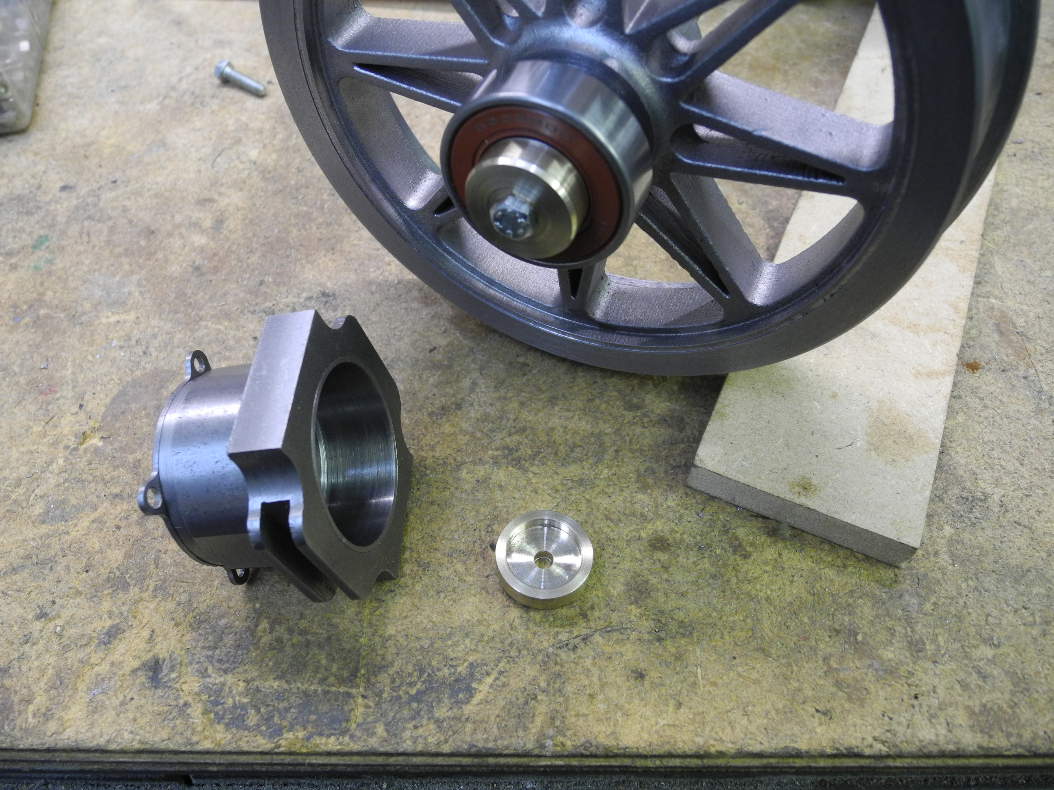
The end caps of the axle boxes were 3D printed in stainless steel.
This photo shows them after printing, still on the building plate of the printer. 

They are fixed with four M3 bolts. 

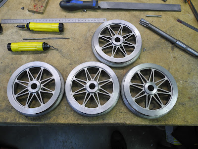
The wheels are glued to the axles.  


The leaf spring with shackles and supports on the wagon. 

The wagon, fully sprung, on its wheels. 


Steps and lamp irons are the last things to make, before starting the paint job. 


The "Märklin train set" 😄 at the Voorjaarsstoomdag 24th of April 2022 in Waalre.
This model engineer exhibition was organized by our club Stoomgroep Zuid. 


Sunday 3 April 2022

Klappdeckelwagen (lidded wagon) (7)

The wheels were the next thing to "make", or rather machining them. I'm a member of a German Live Steam forum, that is mainly about locomotives and wagons on the bigger gauges (5" and 7¼" gauge). 

I've posted the progress of this Klappedeckelwagen on this forum and on one of the photos the wheel castings I had for this wagon were visible. These are wagon wheel casting with 8 straight spokes. Not exactly the correct shape for this German wagon. Some tips were given about the correct pattern for so-called V-spoked wheels.


A wheelset I've photographed at Münsingen railway station in Germany.
This is the location where the preserved Würrtembergische T3 is stationed. 

I even got an offer from forum member Kristian who could make castings from 3D printed patterns (for every wheel a new pattern is printed) at a local iron foundry in Brno. The material is C45 steel and the investment casting method  (also known as the lost wax casting method) is used to cast them. The main advantage of this method is that no drafting angle is needed on the pattern and undercut is no problem. For this wheel with straight spokes, this is a perfect method.

This help was of course accepted and at the beginning of 2022, I received the castings from the Czech Republic. As this is within the European Union this makes importing relatively easy.


The machining of the wheels is a job that takes some planning of the cutting operations but is not really that difficult. The size of the wheels (130 mm on the tread) and the C45 steel, made a low cutting speed necessary. For me, this is one of the bigger jobs of turning, when model engineering. 

I started with a tool with carbide insert plates and a speed of 450 rpm. This worked fine and the chips came off hot (sometimes even blue) and gave a very smooth and shiny surface. Although a nice appearance, it didn't look like the surface finish on real wagon wheels, and in my opinion, it looked more like wheels on an H0 model. 

So I switched back to using a high carbon tool steel. These I can grind myself to shape and it gives a more dull surface finish on the wheel. Therefore the cutting speed had to go down to 140 rpm, so taking some more overall time to machine. However, in one weekend it was possible to machine all the wheels 😀.

I've ground the remains of the sprues off. With these sprues, the wheel pattern was attached to the casting tree.   Removing them makes cutting a bit easier on the lathe tool and lathe. The cut is then more continuous from start. 

Starting with the backside, so I could get a reference plane to start measuring the width of the wheel.  


Then the front was faced and the diameter had its first cleaning up.

Once reversed again, it was turned to width, drilled, bored out with a boring tool, and reamed.  


 A mandrel was made and set up in a collet.

 The front side and rim could now be made to size. The tread is made 3 degrees conical. 

The dimensions are according to international standards. (This diagram is to be found on the website of the DampfBahnClub Deutschland, but on many Live Steam websites you'll find similar tables.)


Only a few wheels, but a lot of chips. Clearing them from the lathe in between was necessary.

At 20 degrees angle, the side of the flange was cut.  Using a mandrel makes it possible to do every operation on each wheel. Leaving the tool setup in the same position and changing the wheels in between. 

The HSS radius tool, for finishing the flange. The left and right sides can be cut by using both sides of the tool in one operation.

The last finishing cut. 


The wheel sets on their axles. Very nice castings indeed!
They will be glued to the axle (Loctite 601). 

The roller bearing  (6202 RDD)   (15 x 35 x 11 mm), is fixed on the axle with a small brass cap.  Of course, smaller bearings would do also for this wagon (no passengers will sit on this wagon), but I had these in stock and they are the same as used for the open Omk wagon and the Beer Kühlwagen. 


The wooden floor was also made. This is made from a 6 mm MDF plate (from an old cupboard), on which planks are glued. 
The planks are cut from old wooden window blinds from my daughter's bedroom. 
Again recycling is used to get material for making this wagon. 😎


Leaf springs are the next thing that is on the list to make, to get the wagon nicely sprung and on the correct height.