Welcome

Live steam models on 7¼" gauge of the Württembergische T3 and on 5"gauge Great Eastern Railway Y14 class

Welcome to this blog. It will inform you about the progress of designing and building live steam model locomotives. The blog contains the description of a model Würrtembergische T3 on 7¼" gauge (constructed between 2006 and 2017), the wagons for this loco (built between 2018 and 2022), and the current project a 5" gauge model of a Great Eastern Railway Y14 class loco (started in 2020)

On the left you'll find the index where you can browse the different articles and on the right you'll find all the extras.  You'll find a brief description of my other locos on the top tabs.
 

Click for the direct link to start of construction series below 
T3 7¼" steam locomotive 
 
Enjoy this site. Erik-Jan Stroetinga. The Netherlands. Europe.

Sunday, 24 November 2013

Smokebox steam pipe arrangements

In October and November 2013 "the front end" was made. This is a convenient name, of American origin, for the smokebox and its internal pipes. The connection to the cylinders was a bit of a puzzle, because, even on this scale, space between the frames and in the smokebox is limited.

A simple flat ring is used to make the connections between the steam pipes and exhaust pipes steam tight. This way of fitting the assembly is easy to insert and adjust. The pipe assembly slides between the flanges, is lined up and the union nut will be tighted. All the union nuts were made of brass rod and have a hexagon of 19 mm. The large union nut is M16 x 1. The small part is M10 x 1 and will fit in to the cast iron cylinder block. 


The exhaust pipe was bent from 12 x 1 mm copper pipe . Two bends are cut in half and then silver soldered together. This sounds more difficult than it actually is.  


Standard copper fittings were used to make sharp bends. 


A test set-up  for the live steam pipe and exhaust.


An off-set has been made for the live steam pipe. This enables easy fitting inside the smokebox, where space for the wrenches is limited.


The petticoat at the bottom side of the chimney. The chimney is firmly held by 6 M5 bolts. If the engine will be pushed along the track to the steaming bays, the chimney will provide an easy part to hold the engine.


A u-shaped plate on top of the frames will hold the smokebox in position.


A friend of mine had great deal of trouble to get his smokebox of his new 5" gauge loco steam tight (and keep it that way during initial steam tests). The problem of sealing the pipes in the smokebox, without the trouble of making and fixing special formed and cut plates and the usage of some kind of packing material was solved with custom made brass bushes.  To get a flat surface to take up the steam pipe and blast pipe, large (26 mm) holes were cut in the bottom of the tubular smokebox.


Brass bushes were inserted, over which the pipes will slide. A ring on the steam pipes will  just touch the top of these brass bushes and seal the smokebox mechanically.


Adjusting the blast pipe, concentric with the chimney. A long piece of 10mm steel rod was used to gently force the pipe in position. The off-set of 8 mm was determined in Solidworks.


The steam pipe just after silver soldering. 


The 'ring' on top of the steam pipe is to be seen just under the screw thread; the top of this ring will just touch the brass bush in the smokebox bottom. This part is screwed in to the main steam pipe, so it can be set to the correct height. Its diameter is a few tenth millimetre smaller than the bore in the bush. This way the pipes and seal slide in position, when the smokebox is inserted in its place from the top.


The blower ring was build up from two turned brass rings. The exhaust nozzle is standing in the back.


Four small removable jets (1 mm) are screwed in with  M3,  on the top of the blower ring. They are set at a slight inwards angle of 5 degrees. 
Use is made of copper grease. The high copper content will prevent wear and sticking of screwed connections which are exposed to very high temperatures.


A top view through the chimney.  The exhaust has an initial diameter of 7.5 mm. The exhaust nozzle is interchangeable. With the aid of a new and very informative book of Wilhelm Wallner  "Strömungen von Dampf, Luft und Wasser in Dampflokomotivmodellen"  (Nackar Verlag) I have calculated the nozzle diameter and settings of the blower.  This German book explains a lot of gas flows in miniature locomotives. It's well written with a lot of practical formulas.


The blower ring in position on the blast pipe. Its relative high position is correct for this long chimney. 

A set-up for soldering a small knee, that will take up the steam pipe for the blower through the smokebox wall.


Ready to take up the main steam pipe.


The completed 'front end'. The main steam pipe on the left (no super heater installed; the original locomotive didn't have one either), the blast pipe with blower and  3 mm. steam pipe for the blower.


The fire tubes are easy accessed for cleaning with this arrangement. My 5" 'Didcot" has a stainless steel radiant super heater, which is very difficult to clean. My 3.5" "Mona" had a copper spear head super heater that burnt out after several years. After a few repairs it was omitted all together and I did hardly noticed a change in the performance of the locomotive, except maybe for a slightly higher water consumption.


Wednesday, 14 August 2013

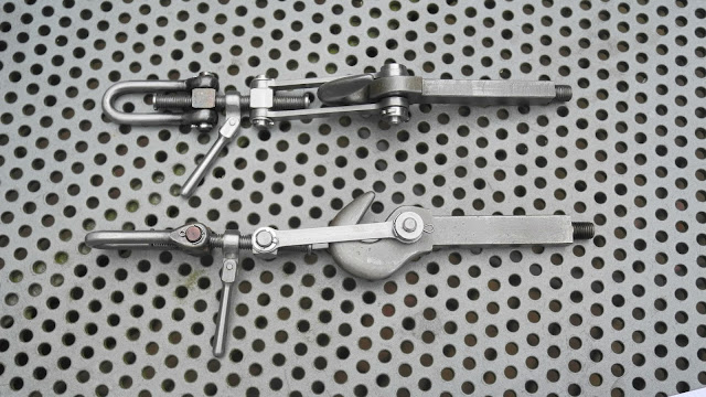
Screw couplings for the locomotive


The screw couplings for the loco were a nice project for starting up after the summer holidays.
I couldn't find a drawing of a newer pair, so these old style drawings were used a starting point for my couplings.

I started with the linkage; a nice job for the CNC milling machine.


The hooks were made a long time ago, when the main frame was made in 2007. With the CNC machine the linkage on the hook was milled in one set-up. They are made from 3mm thick mild steel.


Drilling a 1.2mm hole for taking up the split pin. This pin wil connect the links to the hook.


These links are 46 mm long. In these small details you'll find that 7¼" gauge is quite big.


From square 8 mm mild steel the block was made. One half will have M5 thread, the other M5L (left handed thread).


I've bought nice stainless steel harps, but they were to long. New ones had to be made. A 9.5mm steel rod was salvaged from a old printer, which was very nice materiale to turn.


With a large radiused tool it was turned down to 4.4 mm.


The original stainless steel harps that proved to be too long and a bit too thick. The new ones under production.


Filing the ends with the aid of some filing buttons.


Outer shape that needs to be rounded off with a small file.


Afer completing the filing and sanding the harp is bend.


The handle for screwing the coupling


Most of the parts completed


An impression of the size. It only weighs 93 gramms.


The final coupling; blackened with a propane flame and than dipped in motor oil.


End caps on the spindle, so the parts wil not come a part.


The complete set.


A coupling on discarded wagons in Hombourg (Belgium)


The real coupling on a preserved T3 in Heilbronn. (Nice detail: this loco is being rebuild, but under the frames you see a part of 7¼" track on the shop floor)


Thursday, 11 July 2013

The mechanical lubricator.

Lubricator with twin pumps.  (These will feed the cylinders with steam oil).


This pump is driven by roller clutches. The ratchet wheel is omitted this way, which makes it a reliable system
The clutches were obtained from http://www.pollymodelengineering.co.uk/, the outside dimension is a bit odd (6.52mm) and a special hole had to be turned for press fitting the clutch in the tank. The tank is made off 1,5mm brass and is silver soldered. 
The scotch cranks are driven by a stainless steel eccentrics whit a throw of 4 mm. Here the two cranks are milled from a piece of scrap bronze.


The pump rams are made of 3mm stainless steel and are moving in a brass pump house. A close tolerance between pump ram and pump house is needed. (0.02mm)


The hand wheel and lever were CNC-milled on the new Wabeco machine.
There are two non-return valves  (check-valves), one right under the pump ram and one only 30mm away in the brass housing on the left. I've chosen for two individual pumps, one for each cylinder.


The brass lid was formed over a steel former plate. The tiny hinges were filed by hand.


The almost finished lubricator. It will be placed on the running board, under the water tank. The middle side door will give access to lubricator. 


This is the Solidworks design I've made for this pump. 
I still have to decide if a small sight glass will be necessary. Maybe by just checking the oil level by opening the lid will be ok.

This will be the drive system for the lubricator. Taken from the valve gear and reduced in swing by an intermediate tumbler. The complete lubricator can be removed by releasing two screws, uncouple the oil pipes and drive link and taking it out via the under side. This should make maintenance easier.


The Solidworks view of the loco.


After installing the pump, we found that the oil level in the tank was hard to see. A small sight glass would be useful. The window frame was milled from solid brass and cut of with a large saw cutter


The frame for a 6 mm wide, 24 mm long and 2 mm thick glass. The glass was cut from a piece of glass of an old picture frame.


Making the opening in the tank, and tapping M2.


The opening in the running board. The lubricator can be inserted from the bottom. This makes removal for maintenance purposes easier.


A drain plug on the underside was also added.


A small piece of white coated aluminium (salvaged from an old CD player housing)
was positioned a few millimetres behind the glass. This makes reading the oil level easier under bad lighting conditions. 


The lubricator on the loco, sitting behind the inspection door.


An extra oil check valve has been made, to make sure that the lubricator will give longer trouble free operation and needs les frequently maintenance. Click here to read about this valve.