


There are 8 stainless steel 3D-printed brake blocks that will grip all four wheels. The brake system itself is a close copy of the original, as used on the full sized wagon, but skipping the air brake cylinder.
A support frame for the brake hangers had to be made. I intended to use 20 x 10 mm steel bar, but decided to use U-profiled 1,5 mm steel instead. This is also strong (rigged) enough and is a lighter construction. The total weight of the wagon, according to Solidworks, will be about 30 kg.

The cross members were made from a square tube that was cut in half, and milled straight.

At each end a corner plate is silver soldered, with which it will be screwed to the main frame.

Two small rivets kept the assembly in place, during soldering.

A lot of parts for the brake hangers were lasercut from 2 mm steel. Alas the laser parameters were not optimal; so there was a lot of work to remove the burrs.
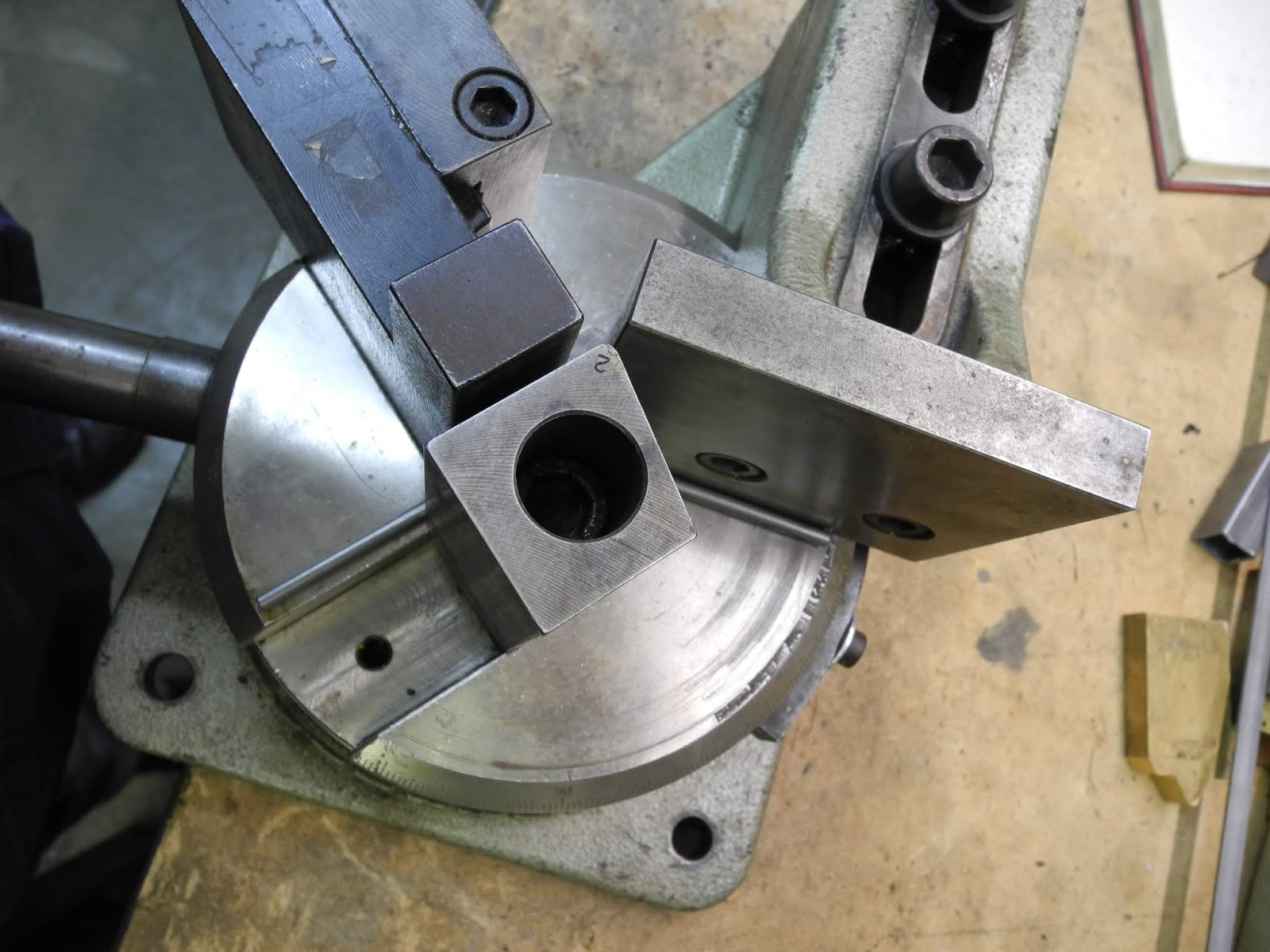
The Gressel HB 20 strip bending machine was put to use to bend rod for the triangle for the brake blocks.


A relative heavy machine for bending such a small rod, but with the end stop, it was easy to bend them all to the same dimensions.

A groove was made with a ball nose end mill. This way they have good contact surface for soldering them to the cross bar.

In a old vice they were soldered to the cross bar.

A primitive, but workable set-up for soldering the connecting plate in the middle.

The finished triangle.

A lot of serie work had to be done. Working in batches can save some time. Most of the parts are therefore made for both wagons.

Work in progress

Disassembling the main frames, for drilling operations.

A first test fitting of the cross members, brake hangers and triangles.

Side supports of the frame, being bend.

These supports are located at the end of the T-bars. Even on this model they give some real support to the side boards of the wagon.

The one under the door, is the only one that has no connection with a T-bar. The visible open corner is therefore soldered, so it resembles the press formed part from the original.

As said: a lot serial work.

A small plate, for gripping the T-bar

On the real wagon the side boards were removable. The lower part of the T-bars is locked in position with this plate.

Next step: middle support frame

Some hangers needed to be changed; in my first design in Solidworks I didn't notice the importance of the size, but they were too long. The tie rods would interfere with the cross members. It was possible to alter them, so the CNC miller was put to use.

Split pins are used to assemble the parts.


A first look at the brake rigging.

Making pitch forks. A set-up in the milling machine with an end stop makes it possible to produce the 14 parts quickly.

The end tie rod; fixed to the support plate.

The brake lever; roughly cut to shape and....

...CNC milled to the final shape.

Two plates, and a big bearing, to take up the force.

The brake lever in position. An extra plate, to make the system rigged.


A first test, where the brake lever pulls on tie rods.

On its wheels, during a recent club meeting.