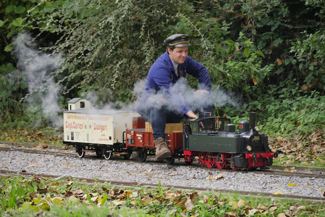
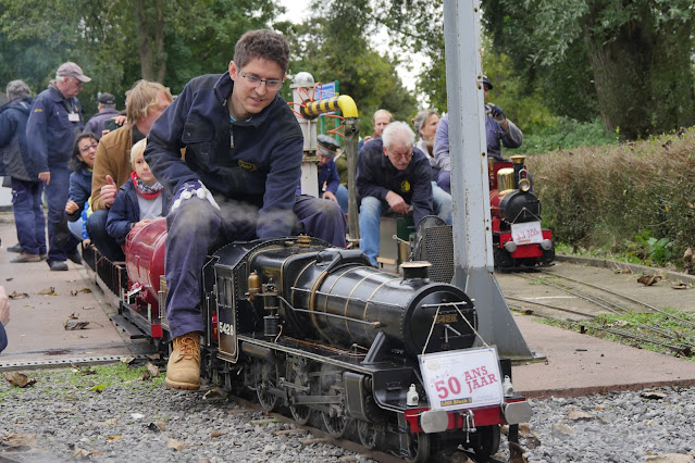
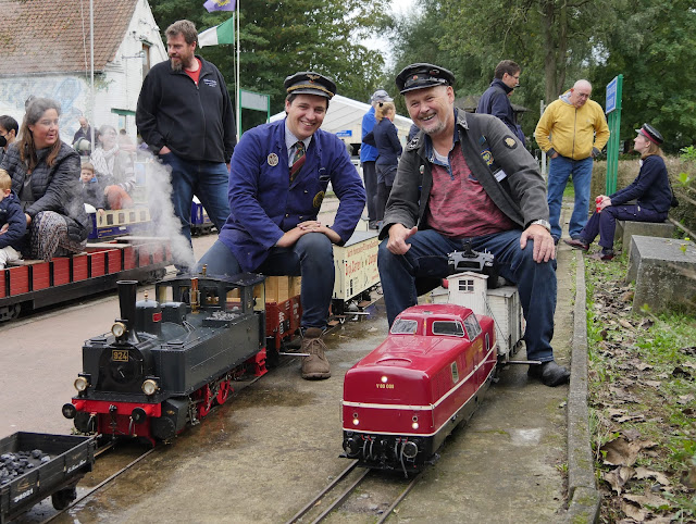
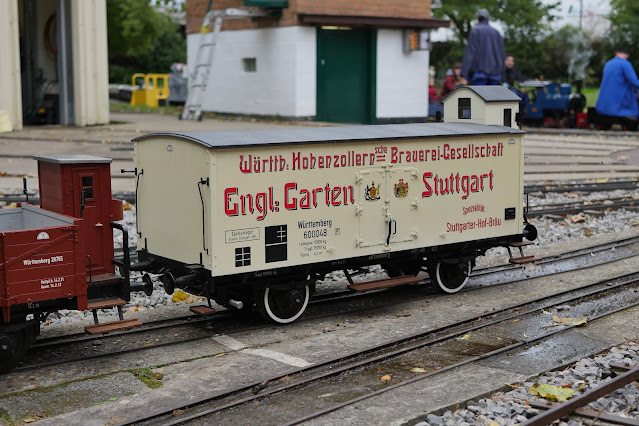
When browsing through my books on German goods wagons, I came across some short-wheel base wagons.
Building one, as a third wagon for my T3 train set, is therefore an option. This is because a shorter wagon can be stored inside/on top of the Omk open goods wagon I build earlier. This way the transport problem is solved: the train set will still fit in the car.
Building another wagon is fun to do and I still have some wheel castings, frame material, and an old steel IKEA wardrobe from my daughter's room. It had to be disposed of and it seemed nice material to recycle.
Also, I want to build a water tank inside this wagon, so we have some cold water available for the injector of the T3 steam loco. The side tanks of the T3 do heat up slowly, especially on a summer's day, and because the water consumption of the loco is low, the water stays too long in the tanks and will get too hot at a certain point for the injector to work properly.

As usual, I start with a model, this time not a Märklin model, but a Fleischmann H0 model
(cat. no. 5213)
The transport solution I have in mind.
Position in the train, as the second wagon.
These wagons were used for transporting bulk goods like chalk and salt. Goods that had to be transported dry and could quickly be loaded by a transport band. This was quick, through open roof lids. But unloading had still to be done by hand and was therefore slow. This is why these wagons were further developed over time and eventually were replaced by more modern self-unloading wagons with sliding roofs and drop doors on the side and/or bottom.
A lot of these wagons survived until the late 1960s as storage/waste wagons at locomotive sheds. This one is used for storing firewood for their steam locos. The brake man's cabin, that it originally had, has been removed.
A bit of paint would not be bad. But the details of the lids are clearly visible; which is a great help when making the Solidworks drawing.
The 1 mm steel plate was recycled from an old IKEA wardrobe. With the angle grinder, I removed all the edged sides, so I had flat sheets to start with.
This is one of the side panels, cut to size, measuring 235 x 160 mm. The paint makes it easy to scribe the bending lines on the metal.
Bending is done with the sheet metal folding machine.
setting up the individual bending dies
The length of the die is chosen accordingly to the length of the bending line.
Some correction is needed afterward because of the deformation of the plate. The 1 mm plate is becoming quite ridged after these bends.
Cutting the end plates with the guillotine shear. A front stop and angle guide are used to cut the 110 degrees corners.
The size seems big enough to store an oil can.
A temporary setup on the workbench, to get an impression of the size. After all these years of using 3D Cad software, and looking at models on the computer screen, it is still difficult for me to get a good idea of the real size of the parts drawn. 😏
The appearance in SolidWorks


