Welcome

Live steam model on 7¼" gauge of the Württembergische T3 no 924

Welcome to this blog. It will inform you about the progress of designing and building live steam model locomotives. The blog contains the description of a model Würrtembergische T3 on 7¼" gauge (built between 2006 and 2017), the wagons for this loco (built between 2018 and 2022)  and a 5" gauge model of a Great Eastern Railway Y14 class loco (started in 2020)

On the left you'll find the index where you can browse through the different articles and on the right you'll find all the extra's. On the top tabs you'll find a brief description of my other locos.


Click for the direct link to start of construction series below 
T3 7¼" steam locomotive 
 
Enjoy this site. Erik-Jan Stroetinga. The Netherlands. Europe.


Sunday 23 January 2022

Klappdeckelwagen (lidded wagon) (4)

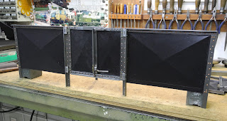
The Klappdeckelwagen (lidded wagon) has its name from the 'Deckels' (lids or top doors) that cover the top of the wagon. Six lids are to be hinged at a central beam on the top of the wagon. 

They can be opened, but only in a certain order. First, the middle one has to be lifted, and then the right or left ones can be opened. This is due to the rain gutters that are attached to these lids. 

Because the goods (chalk, zinc ore, salt, and such) had to be transported protected from the weather, the lids were designed with rain gutters. For the model of this wagon, this is not really necessary, but I thought it would be nice to try to make these gutters. 

The lids themselves are made from 0.8 mm steel plate (recycled from an old Ikea wardrobe) and are bent the same way as the side walls and doors made previously.   


First, some work on the end plates had to be done. 
Riveting the support beams on the end plates. 

This gives these plates their rigidity. 

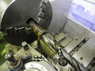
Drilling in the buffer beam, for fixing the support beams to the frame. 


The U-shaped top beam is made by sawing a 25 x 25 mm. square tube in half.  

Milling the top beam to size. The workpiece had to shift several times in the vice.  

Two angle plates secure the top beam to the end plates. 
This kind of construction details I take directly from the works drawings of this wagon.  

With a special narrow bending die, the top side plates are bent. 
Due to two bends in opposite directions, this narrow bottom die was needed. (This is a homemade die.)

The top side plates are in position. 

The lid plates are cut to size and scribed. 

After the first bend over one long diagonal (220 mm), the second and third bends are made separately over half the diagonal (110mm). The top dies are set up to the according to length.

With a front-end stop, the rain gutter is bent. Several small bends give the round shape. 
The front stop is moved each time a few millimeters. 

Drilled and the ends cut to size, ready for riveting on the lids. 

The gutter. Two rivets will be placed later on; they will be used to hold the door handles as well. 

The rain gutter on the right, is seen from the underside.


A jig for drilling the holes for the top gutter.  A lot of rivets will be used. 😄.  
The jig is one of the side profiles. Although I thought I have taken the greatest care to make them in pairs (left, right), I still made a mistake: it was mirrored. 😕 

A first test fitting (hold in position with some magnets).
Because I have bent the plate (and not deformed it with a deep drawing process), there is a deflection/deformation on the sides. The side profiles and gutters bring them back in shape. 


The next thing to do is to make the hinges. 


The Solidworks drawing with more details added. 


Thursday 6 January 2022

Klappdeckelwagen (lidded wagon) (3)

The frame and superstructure are becoming shape.
To determine the correct length of the frame beams, I had to make the door hinges first. With this design of these hinges, there is no way to correct the 'hanging/positioning' of the doors in the door frame. To adjust this there is only one 'parameter'; the length of the frame. 

 By making the hinges first, it is possible to measure on the job how long the side walls will be overall. This will determine the length of the frame.

The bodies of the hinges are made of 6 mm steel strips....

.....milling....

....drilling and reaming....

....tapping M2....

.....filling round....

assembly on the side walls.

Cutting 1,5 steel plate for the second half of the hinge

Bending the lug with a small jig in the vice.

Closing the lug. 

The bent lug. 

Scribing the exact position of the lug. 

Each lug is made to size to its location on the door.

After that, the lip is made to width. 

Riveting to the door.


A small gap between the door and frame is left. This is necessary for the paint layer later on. 

One part of the side wall with door. 

Test setup of the complete side of the wagon. 

The exact length of the side wall can be measured and the frame beams can now be made to size.

These hot-rolled profiles (40 x 20 x 5) are not fully straight.
They are adjusted by bending (pressing) them into shape. 

Drilling the holes for the corner pieces and the horns.

The first assembly of the frame.

The superstructure on the frame.  


Brackets that support the vertical beams to the frame. Although they are small and only made of a 1,5 mm plate and fixed to the frame with two M2 bolds, it is surprisingly ridged.

The side walls are fixed to the frame. 

A long 10 x 10 x 2 mm support beam for the bottom part of the side wall. 
With the NC control of the milling machine, the position of the rivets (interval 11.5 mm) is set out.  

A first impression of the wagon. 


Klappdeckelwagen (lidded wagon) (2)

An update of the Klappdeckelwagen. The previous half year there was not much time for model engineering due to a lot of work at our university of applied science. But now with the Christmas holidays, there is more time; we still have a lockdown here in the Netherlands, so not much outdoor activity. 


The buffer beams, horn plates, etc. are the same as for the wagons previously described on this blog. 

The side plates are strengthened with L-profiles (10 x 10 x 2), which are riveted with 1,7 mm copper rivets. 

Just before riveting, Loctite is applied between the parts. This way no water can come in between the plate and profile when the wagon should stand in the rain. 

Positioning the profiles dead square. 

John came along. He is also making a Klappdeckelwagen but in 5" gauge.

His version is a later version of the wagon, with a longer wheelbase and on the lids these square shapes.
Even that was possible to bend. 


John's long wheel-based version in 5" gauge.

Brawa model to be released in 2022


The long wheel-based modern version versus the earlier short wheel-based version. (Roco H0)


The supports for the door handle mechanism.

The doors are of the same design as on my open wagon. The Germans Railways had from early on a lot of standardization in their wagon building programs. 

Even the Klappdeckelwagen has the same construction details as the steel coal wagon. 

And even in making models of German good wagons, standardization pays off because a lot of punches and dies I've made can be used again.  

Bending the door handle in the vice.

The doors.

The coupling hook is CNC milled.


A new (secondhand) computer is now in use to control the CNC miller. 

Profiling the backplate of the buffer stock.

 
Drilling a 16 mm hole for the buffer stocks. 

Work on the buffers.


The cross slide is set in several stages to angles between 2 and 6 degrees, to obtain the shape of the buffer head. 

The buffer beams were completed.