The smokebox doors I made for my other locomotives were usually crafted from preformed steel disks, two millimeters thick. These were produced by stamping a round disk using a radiused forming plate. That was possible back in 1984, during my internship at the main locomotive workshop of the Dutch Railways in Tilburg.
Alas, that locomotive workshop no longer exists. However, the area has since been transformed into vibrant public spaces—including restaurants, schools, shops, and a library. See this link Spoorzone Tilburg. Many of the buildings are still recognisable and even the locomotive roundhouse and turntable is fully preserved. This Dutch book tells you all about the history of this once great locomotive workshop.
I had a few disks made back then, but they've all been used. So the door for this smokebox was turned from a solid steel disk.
 The original GER smokebox doors were at first of plain dished pattern flush with the smokebox, however from
 1915 onwards, the GER introduced a redesigned, more robust and heavier version with bevelled edges and a surrounding ring. I’ve adapted my design to reflect this later style, which had been fitted to all locomotives by the time they came under LNER ownership in 1922.

In addition to the revised door shape, an extra ring has been added to the smokebox.
This ring was turned from the same steel disk that was later used to make the smokebox door.
The ring fits inside the smokebox and reinforces the front plate, making it more rigid.
The remaining portion of the disk is used to machine the smokebox door itself. I started by opening out the back side of the door, allowing it to be clamped in the three-jaw chuck (in reverse) so the front side can be worked on.
The inner side of the door has a stepped recess; the outer step—measuring 90 mm in diameter and 6 mm deep—can be gripped internally by the jaws of the chuck. This provides a stable setup for the next turning operation on the front side.
On the SolidWorks drawing, I added stepped segments to mark the curvature of the door’s 190 mm radius—essentially a poor man’s CNC. I used a small table for the corresponding X and Z coordinates for each step.
Using a right-hand cutting tool, the stepped contours were transferred from the drawing into the metal.
These machined steps now serve as indicator marks on the surface of the door.
In the 1982 edition of the Dutch model engineering magazine De Modelbouwer, there was a description of a lathe technique called “turning with a slipping tool.” This method involves leaving the toolholder slightly loosened on the toolslide, allowing it to rotate around its axis
At a slow speed, the radius of 190 mm was formed by manually guiding the tool along the toolslide, removing the excess metal between the previously machined stepped grooves. Light cuts were used throughout, with frequent adjustments of the tool toward the surface, aiming to cut only between the grooves. During the final pass, the grooves themselves were lightly touched, blending them smoothly into the finished contour.
I've used this method many years ago on my Gauge 1 Royal Scot, but I was surprised by how well it worked on a 5" gauge locomotive. It looks more challenging than it actually is.
The door hinges were machined from 5 × 5 mm steel bar stock.
The outer end was radiused using file buttons.
The hinges were bent to match the curvature of the door. A 22 mm guide plate—made from scrap metal, drilled to align with the center of the door recess, and bolted in place—was used to mark the hinge position on the door.
The holes were drilled to accommodate 2 mm steel rivets.
The second hinge was clamped onto the door, ready for drilling. Its holes were transferred directly to the door to ensure precise alignment—at least, that was the intention.
However, I forgot to check whether the hinge pin was perpendicular to the door. The hinge shifted slightly during clamping and couldn’t be corrected afterward, so a new hinge had to be milled.
The rivets are countersunk into the hinge. Once riveted, they are filled and finished flush with the surface.
The shaper was used to machine the crossbar, which was made from a 2 mm stainless steel strip.
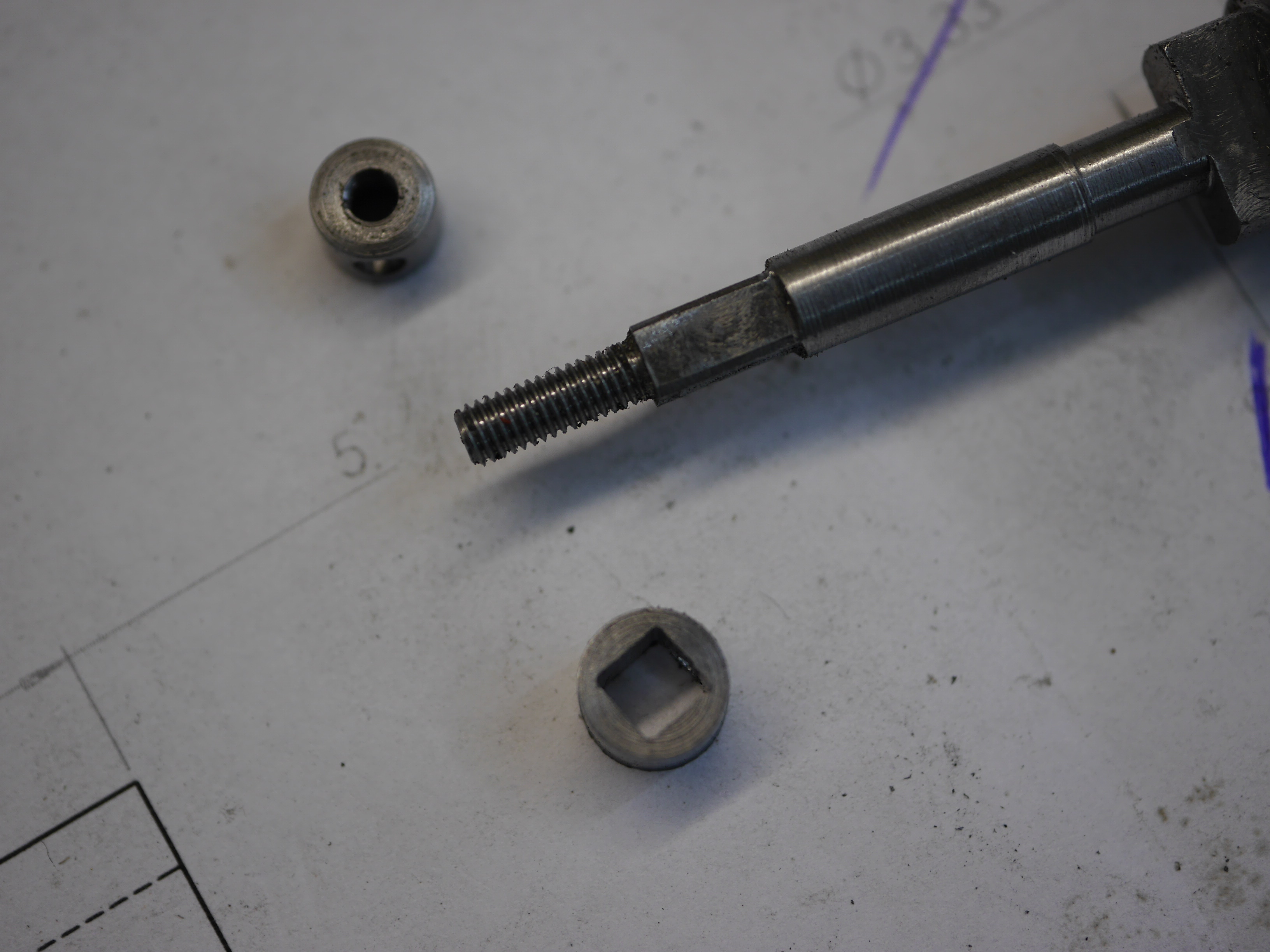
The dart is turned and milled from stainless steel rod.
The square feature was milled using the dividing head on the milling machine, while the square hole was finished by hand with a square needle file.
The handles were silver soldered to the bushes. On LNER locomotives, both door handles are the same length.
A marker tool was made to accurately locate the position of the fixed hinge component on the smokebox.
The door was locked into its correct orientation, and the marker tool was placed over the hinge pin. A light tap with a hammer marked the center of the hole to be drilled.
Two copper brackets were fabricated from scrap sheet metal—specifically, from the material that had earlier been removed when cutting out the smokebox door opening.
The bracket was bent using a hammer to match the inner radius of the front of the smokebox.
The rivet holes were concealed beneath the steel ring during final assembly.
The brackets secure the crossbar in position, which can be removed to allow access for cleaning the smokebox once the locomotive is in service.
A stainless steel heat shield was turned in the lathe, clamped between two steel pieces. Friction alone provided sufficient grip to machine the outer diameter, which had been pre-cut with the shear beforehand.
The heat shield is secured with two small stainless steel M2 bolts, with holes tapped into the boss of the door to accommodate them.
(The brown paste you see in the picture around the dart is copper grease, used to prevent seizing.)
The completed door fitted to the smokebox.
Bending the cover plate was done in February 2025. With the aid of two round bars setup in the bending machine, this was simpler than I even expected. First time right 😀
The lower bar, moves it selfe during the bending and follows the top bar
Shown here with the hinged cover plate beneath the smokebox. The black-and-white photo adds a distinct visual effect, though this is not the famous
Stratford locomotive works where the original locomtive was built.