
The crank axle is more complex, but not too difficult to make. Recently I've made a new crank axle for my 3½" 'Mona' steam locomotive. This is the same working procedure, it is only a bit bigger.
In fact, it only consists of three different parts.


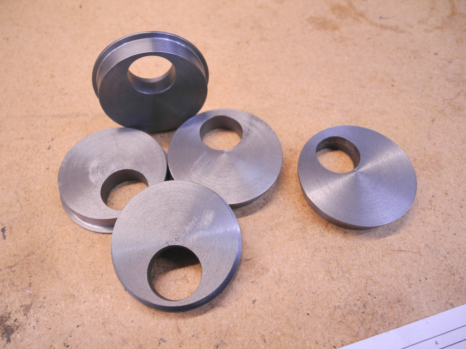
The excentrics

A round bar, which was first turned to the correct outside diameter, is then set up in the independent four-jaw chuck. The excentre stroke was scribed with the height gage, and a center was drilled on the drilling machine first.

The axle hole is bored out with a standard boring tool

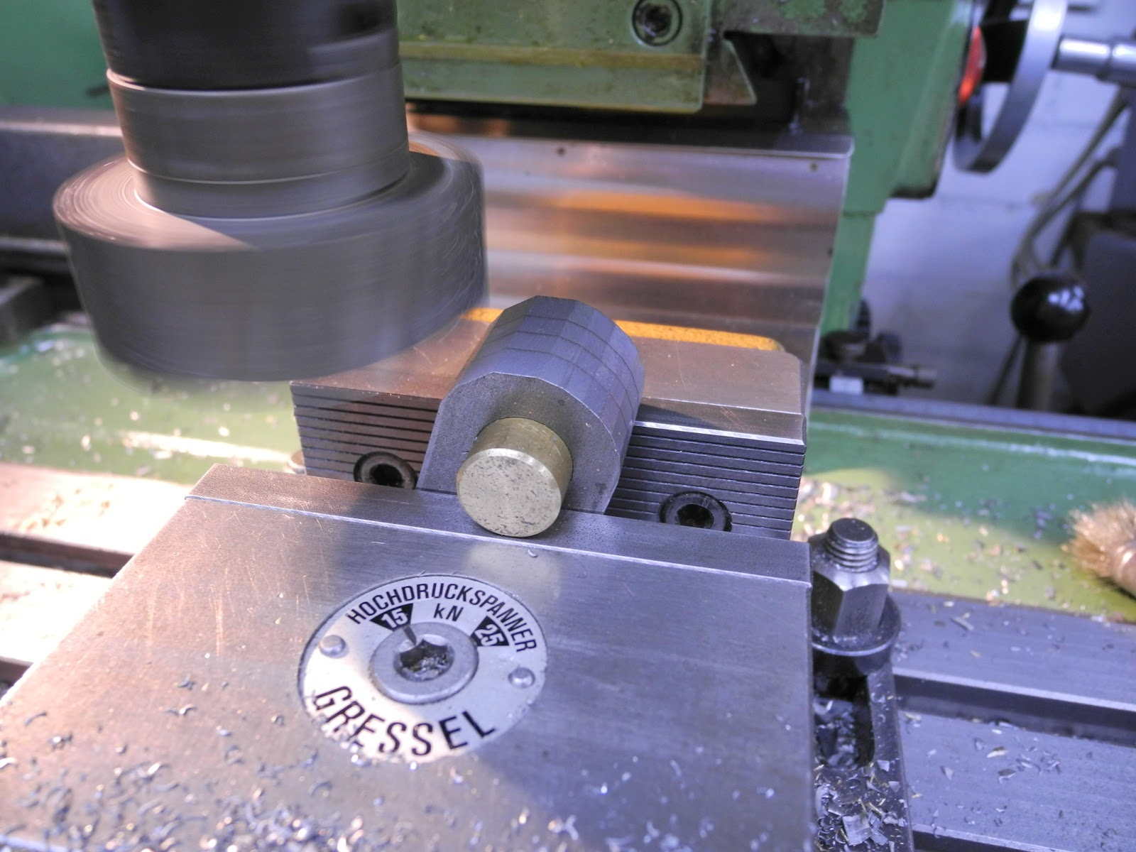
After that, a set up in the three jaw chuck is used to turn the diameter of the excenter.

The parting tool was only used for a limited depth, because it was not possible to support the material.
The rest was cut by a hand hack saw. The back was faced, holding the excenter in the jaw. A piece of thin brass protects the surface of the excenter.
There was just enough material to make an extra spare part.


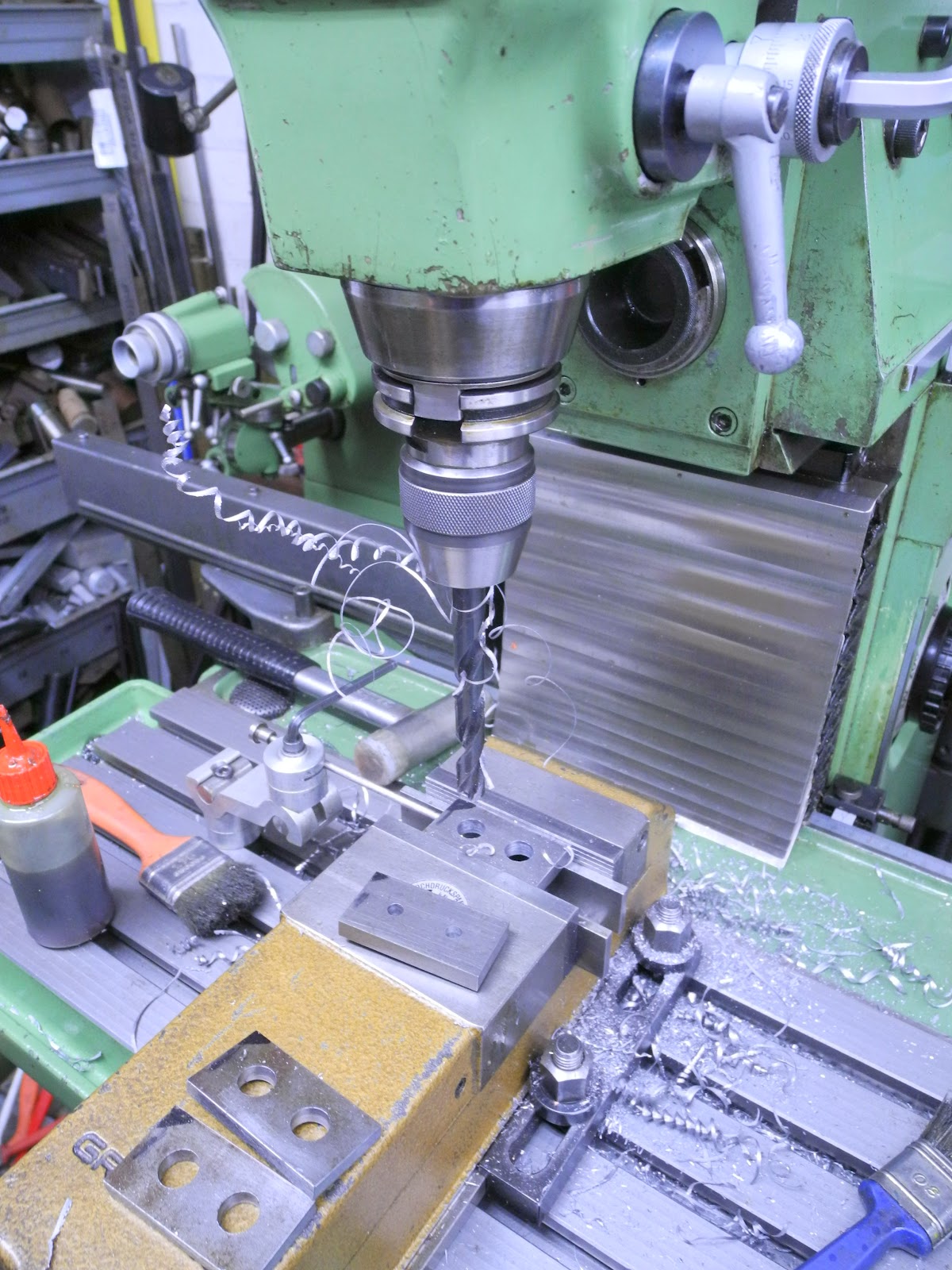
This way the location for the 3.5 mm hole could be marked.

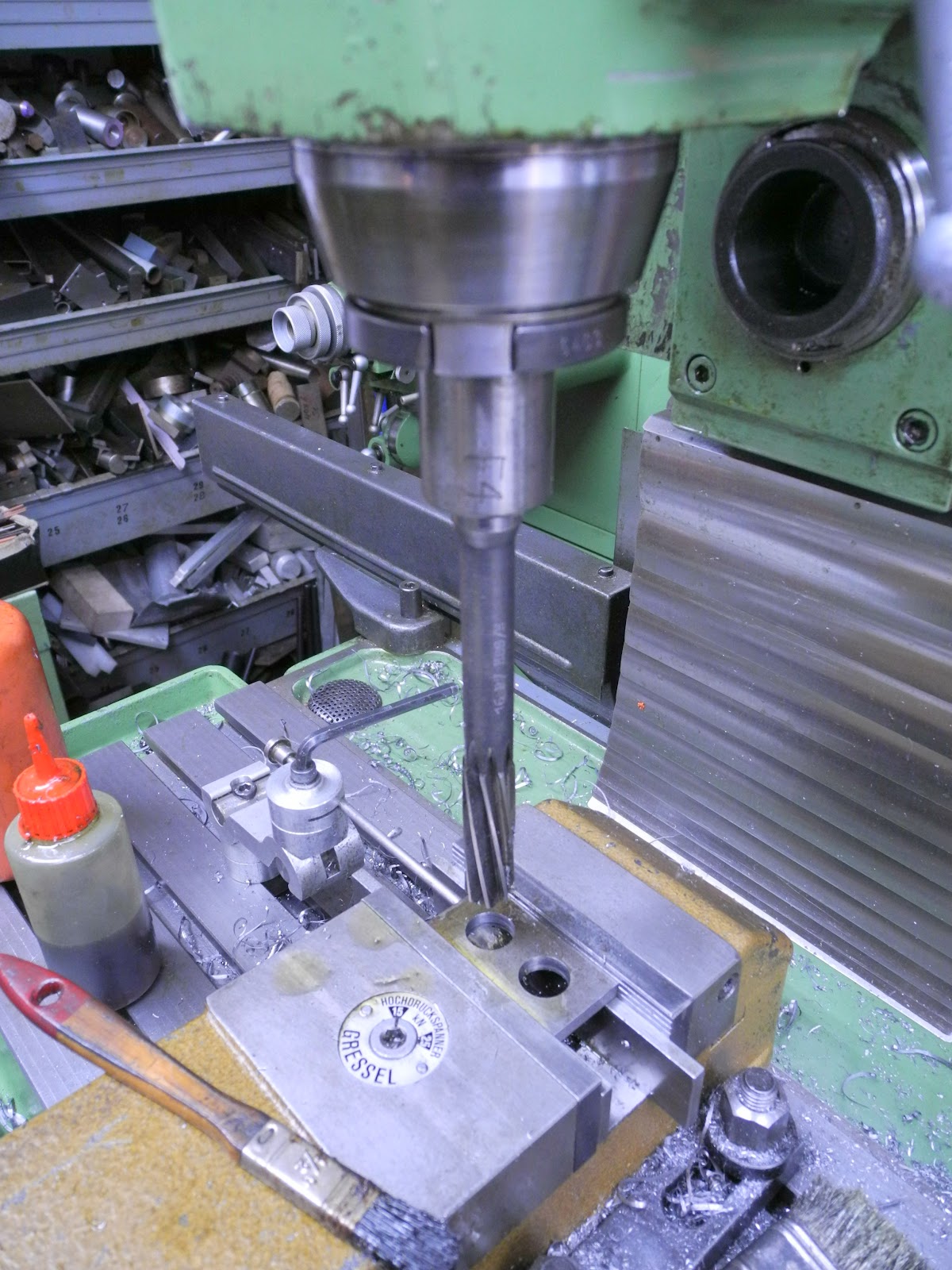
drilling and..

.. taping M4
The crank webs
In the milling machine, the holes for the axle were bored and reamed

A quick test fit, to check that the holes are nicely aligned.
Roughly milling the radius on the webs


After milling they were filed to shape, with the aid of filing buttons.
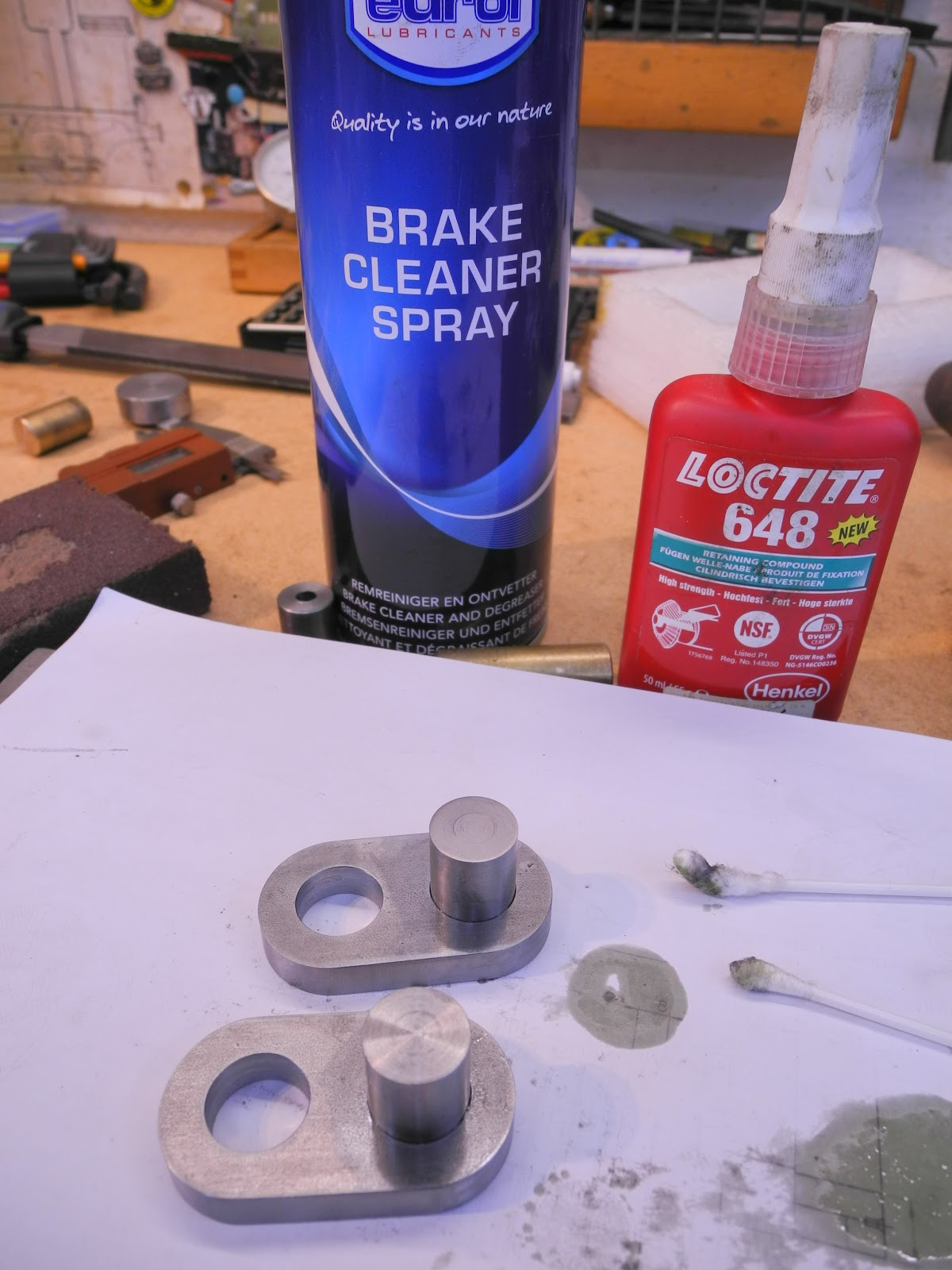
The crankpins are glued. Cleaning the surfaces was done with brake cleaner spray. This works very well; the Loctite then cures fast; within 30 seconds.

The second web is glued in position on the axle. A gauge strip of 10 mm is used to keep them aligned.

The major components of the crank axle.

Center drilling the location for the roll-pins on the milling machine

The first crank is shifted on the axle and glued at 15.75 mm from the end.
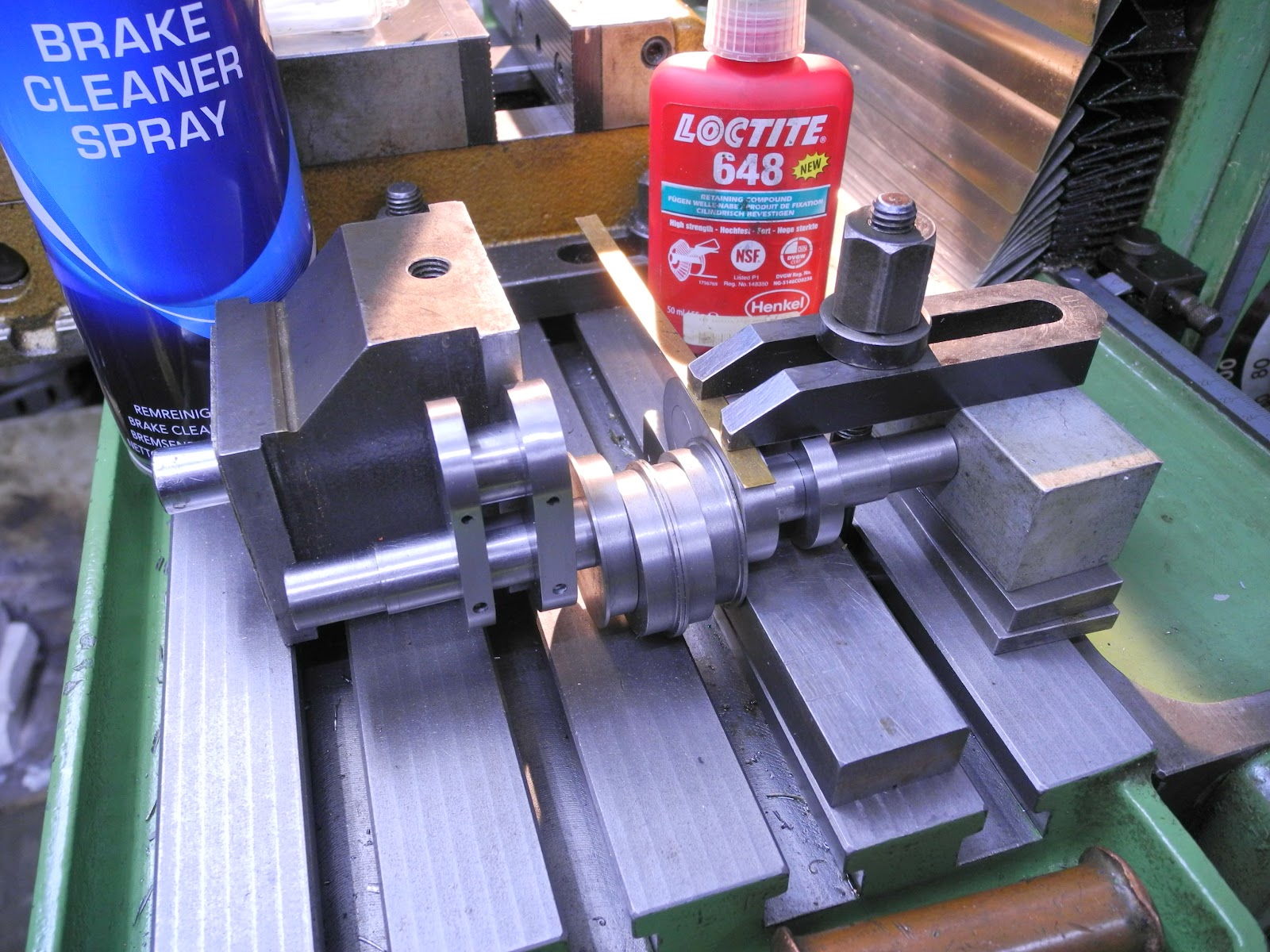
After curing, the second is glued on. A clamping set up is used on the milling table, and with the aid of magnet blocks it can be set to 90 degrees.

I had to look at the drawing several times, to make sure that the right-hand web is leading.
This is not that important, but is a general practice by British locomotives to have the right-hand in the motion leading.
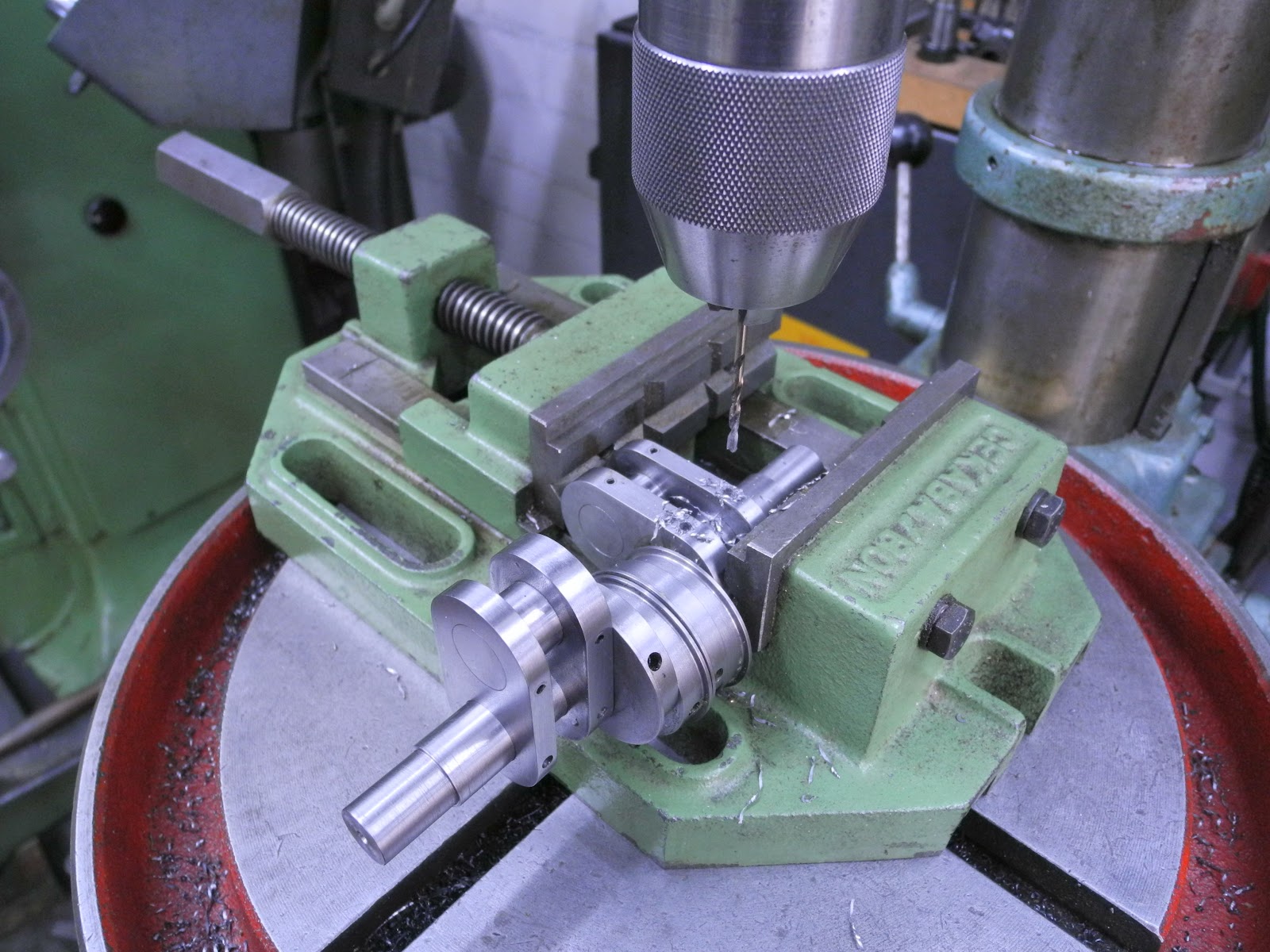
After the glue has fully cured (about 24 hrs), the holes are drilled 3.1 mm, for 3.3 mm roll-pins.

The roll-pins are pressed in. I'm not sure if the pins are needed, with the crank axle of the 3½ Mona they were not installed and so far no problems. But then again this is a bigger crank axle on 5" gauge.

The last stage is milling out the axle between the webs. By the axle that I recently made for the 3½" Mona, I did cut it out with a hack saw and filling. This is a quicker option.

The last thing to do was to set the excenters. Their position was determined in Solidworks. In the drawing, the angle can be measured as a distance to the axle center. This value can be set on the height gauge. By turning the excenter and carefully touching up, they can be set and locked.

The complete crank axle.