
2024, a new year, and finally time to get in the workshop again. The last half year was extremely busy at school and the spare time was used to design the boiler of the new loco.
It's a standard design of a round-topped copper boiler as used for 5" gauge locos. But for this Great Eastern Railway Y14 loco, it had to be adapted to the dimensions of this model and to comply with the safety regulations, and to get good steaming capabilities.

The 3D model is also used to do a FEM analysis, with which the strength of the boiler can be calculated and tested.


The deformation of the 3D model looks extreme with the test pressure of 12 Bar, but this is shown in an exaggerated scale so it is clearly visible where the maximum deformation will be. It's only 0.06 mm.

As described by Martin Evans in his book on model boiler design, I've used no longitudinal stay rods, but horizontal girder plates on the smokebox tube plate and backhead plate.
I've used longitudinal stay rods in previous boilers (3,5" Mona, 5" Didcot, and the7¼"T3), but felt that they are of little use because after fitting (screwed type) there isn't much tension on them after a steaming season.
Martin Evans used these girder stays on several loco designs with success, so a reason to try this for a change.


The first parts we made for the boiler are the backhead plate, firebox backplate and firebox tube plate.
Toin milled from 10 mm thick aluminum the former plates with his CNC miller.


The first step is cutting the copper roughly to the size of a 3 mm sheet.
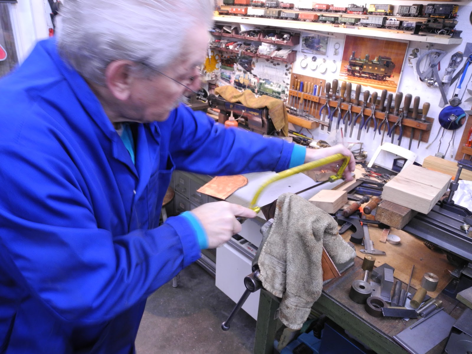
Corners are cut in the vice. The cloth on the workpiece is there to dampen the noise of the sawing a bit and to prevent getting cuts in your hands in case the saws slips from the material. (especially when starting a cut under an angle)

It is of course possible to cut the plates closer to size, but doing this later on during the forming stages works just as well.

Annealing the copper makes it softer and easier to work with. Also, this will prevent cracks in the material during the forming process.

After heating, the copper can be left to cool by air, or quenched in water. The effect is the same, but it is quicker.


Holding the plate between two former plates (one on the front and one on the back) in the vice and the forming can start. Simply beating the edge with a hammer, going around the full circumference.

During this hammering the copper will get hard again. You can feel the resistance in the hammer blows. Then it's time to start annealing again.


The two back plates are ready to heat up once more.

After several stages, the final edge appears.
It's necessary to do this in separate stages, to prevent wrinkling the material.

The fifth and final heating phase.

The time to finish the edge and bring it to a good fit to the former plate.

The surplus of material is cut away with the angle grinder.

Removing the burs.

For the final operation: with a steel hammer the material is gently brought up to a close fit to the former plate. By sliding the hammer over the workbench (and not lifting it), the edge is getting nicely square.

By inserting a small wooden strip between the former and the copper backhead, the two are separated.


A test fit between the frames.

The firebox plates are treated the same way

The small corners on the top of the fire box plates require more attention and to prevent wrinkling the plate, it is necessary to anneal more often.

Eight heating phases in total were needed to form these firebox plates.

In between every phase, the surplus in the corners was removed.

Because there is a lot of deformation in the corners, care should be taken to evenly hammer the edges and to keep the gap between the plate and the former constant. Due to the compression of the copper in the corner, the material thickness increases to 3,4 mm.

The former plate itself was a guide for the amount of material to be ground away.


The last bit was done by hand. With the file, you have more control to get the edge to the final size.

The plates for one boiler.
In the right corner an old disused firebox tube plate of my 5" gauge 14xx loco.
The first parts of the new boilers were completed.