Welcome

Live steam model on 7¼" gauge of the Württembergische T3 no 924

Welcome to this blog. It will inform you about the progress of designing and building live steam model locomotives. The blog contains the description of a model Würrtembergische T3 on 7¼" gauge (built between 2006 and 2017), the wagons for this loco (built between 2018 and 2022)  and a 5" gauge model of a Great Eastern Railway Y14 class loco (started in 2020)

On the left you'll find the index where you can browse through the different articles and on the right you'll find all the extra's. On the top tabs you'll find a brief description of my other locos.


Click for the direct link to start of construction series below 
T3 7¼" steam locomotive 
 
Enjoy this site. Erik-Jan Stroetinga. The Netherlands. Europe.


Sunday 10 February 2013

The axle boxes, horn blocks and springs.


The axle boxes are the so called split type. The upper bearing is made from bronze, the lower part from brass and the axle box from mild steel. Of course everything could be made of bronze, but I had no material available in this size. One could ask if the split bearing type is necessary, but I would like to able to remove the bearings, without removing the wheels from the axle. I must state that I’ve this type of axle boxes on the “Mona” (3.5” gauge) and “Didcot” (5” gauge) as well………and had never to remove the boxes jet.


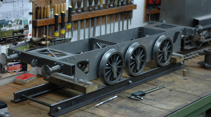
Due to the relative small wheel diameter (138mm) there is not much ground clearance for the spring hangers. If I would use the same design as with the Mona and Didcot, there is a possibility that in case of a derailment (not uncommon on 7.25” gauge ground level track I’m told) that these spring hangers would get seriously damaged.


I could have made a design with the springs on top, but that would coincide with the boiler.
 
So I’ve drew up a system on which the springs are positioned inside the frame beside the axle box. The springs are fixed between a bar on top of the horn blocks and one bar below.


Milling of the horn blocks from square brass bar.


This construction is quite strong and the lower bar acts like some kind of skid plate in case of a derailment. 


For the necessary oiling of the axles, each axle box has a milled recess on the top, which has a drilled hole that is in connection with the bearing below. 


Tribology theory taught me that it is unwise to feed the oil to the axle on the top. There is a 
hydrodynamic lubrication: This form of lubrication occurs more or less naturally in properly finished, sized, and lubricated holes and shafts. Essentially, rotation of the journal causes it to drag lubricant into a wedged-shaped channel generating a load-carrying pressure. The lubricant in this wedge creates sufficient pressure to keep the journal riding on the oil film. This form of lubrication is generally preferred because it is simple and dependable.
An oil feed hole on top would partly destroy this build up of pressure. So why use it anyway? There is a quite simple explanation, I found in a reprint of an old German locomotive handbook. 
Indeed the oil film 
build up of pressure is not as good as it could have been, so most of the wear of the bearing would take place on the top………just were you want it. The locomotive “would sink deeper in the bearings” and that is easy compensated by the springs. The wear over the horizontal line of the bearing however will be less, because the oil film is there not interrupted by an oil feeding hole. And exactly on that position are, on a steam locomotive, the greatest forces due to the movement of the driving rod and movement it translates from the piston to the frame. 


The manufacturing of the axle box is a straight forward milling job.


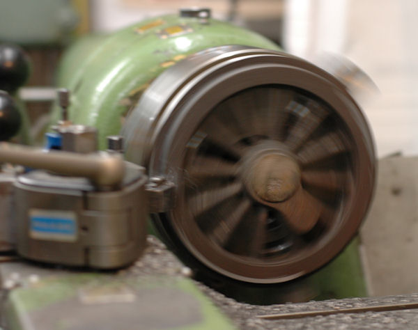
The boring of the hole for the axle was done in the lathe. The set up for machining this hole was done in the 4-jaw-chuck. To get the hole exactly in the middle, a small pilot hole was first drilled in the milling machine (with the aid of an edge-finder this is precise and quick). Once the job is transferred to the lathe, a fixed centre point is put in the pilot hole and the centre is supported with the tail stock. A dial test indicator is put on the centre, and by adjusting the jaws the reading of the indicator can be set to zero.


The hole for the axle is on this loco 22.04 mm. First the hole is drilled up to a diameter of 20 mm. The last 2 mmare turned with a boring tool. Reaming is also possible, but I didn’t had a parallel reamer in this size and find that the lathe boring tool gives a better and more controled finish.


On top of the axle box I’ve made a small lid, which can be opened and closed with the tip of the spout of an oil can, which conveniently fits through the spokes of the wheels from the outside. The lid should prevent to get dirt and grid in the oil reservoir, which is always around when driving on ground level track. The lower part of the axle box has a milled groove, in which a piece of felt will be fitted. This should make sure that, even in the event that the oil reservoir is running empty, a small quantity of oil will keep the bearing lubricated.


A simple set-up for pressing the hinges of the oil cover.


The mild steel plate is only 0.75mm thickness and is cut from the housing of a dvd-rom player


All the parts ready for assembly.


Turning of the wheel castings


The frame looked some what strange, with the unmachined wheel castings standing along side. So the next job to tackle was to turn the wheels. The castings are of a very good quality and they were easy to machine.


The castings from Live steam service; there are of good quality iron.


The set of six wheels during production.


The first operation was to turn the outer rim clean. Now it could be held on this rim in the chuck and the front face and tread were 'cleaned' also. By 'cleaning' only a small amount of material is removed, just enough to get rid of the rough surface of the casting. Once this is done, the wheels have so called reference side or face, on which they can now be hold to turn the back of the wheel. In this operation the wheels get there final width dimension. In the same setting the hole for the axle is drilled and bored to final close fit dimension  of 18mm (tol. 18.00 - 18.02mm)


Profiling the tread is done is various settings. The wheel is therefore clamped  on the faceplate with the aid of a mandrel which is hold in a collet. The wheels tread is 3 degree coned. These wheels are, with a diameter of 138mm, even a few millimetres smaller than those on the GWR 0-4-2  "Didcot".


The wheels are fitted on 22mm axles. I've took one to the club track of the SMMB in Tilburg for testing.


A quick set-up in the milling machine was made for drilling and reaming the crankpin holes. No complex jig is needed, only a pin of (in this case) of 18.01 mm, that has been screwed and fixed in T-groove on the table. The wheel is clamped on the table and machined.  Without moving the table of the milling machine, all wheels were treated in the same manner.

The frames

The frames
With Inventor 3D modelling software I set out the first sketches and the data was used for laser cutting the main frames. Measurements were taken from works drawings of the book and from the Brawa H0 model. Later on I took measurements from one of the preserved locos in the Landesmuseum für Technik und Arbeit Mannheim.    

The mainframe and frame stretchers are laser cut in 4mm steel plate. These were the first parts of the new locomotive project in the work shop. It took me 11 years to build the 'Didcot', so only time will learn how long it will take me to complete this locomotive.


A test assembly for the frames.


The buffers and coupling hook


With a total length of 1.10m even the frame is quite heavy.


Giving an impression of size: At the top the 5"gauge GWR 0-4-2 'Didcot', below the 3½"gauge 0-6-2 'Mona' and in front of it, the 7¼" frame of the T3


Small steel angle profile (10x10x2 and 15x15x3mm) was used to erect the frames. Buffers are turned from mild steel bar, the coupling hooks are cut from solid steel bar. I always like to make these parts in the beginning, to get an impression of the size of the loco.


''Choice of Model"


Photo Harald Frank


The locomotive
This new project will be published on this site as progress gets along. The locomotive is a German Württembergische T3 which I'm designing with the aid of  3D cad software.  I've bought a model of the loco from Brawa. This H0 fine scale model, a book of the loco  and some photos of the preserved locos are the basis for this 7.25" design.
For its scale (1:8) this is a quite small locomotive, with the benefit that it hopefully still can be handled in my workshop. A larger loco on 7.25" gauge would be too much for my small workshop. And in my opinion most model live steam tracks in the Netherlands have the size of a branch line rather than a main line. Although the small size of this loco there are several 7.25” versions of the Prussian T3 and they are all very good performers on the track. They are in main dimensions very similar to this Königlich Württembergische Staatseisenbahnen (KWStE) version and as in real live these is also derived from the Prussian T3.
With an overall length of just under 1.10 meter and a weight of around 100kg the model should be able to do some work on a ground level track and it still can be transported in our family car.


The choice of the model

(Click on the small images to get a larger view)
It all started with the plan to build a small Stroudley Terrier A1 class 0-6-0 loco called New Port and designed by Don Young. A nice little engine on 7.25" gauge (184mm) was the next project after the 'Didcot'.
The wheel castings for this loco were (and still are)  however exceptionally expensive at Reeves2000. Over 600,-- Euro for six wheels
, ex. postage & package.
I was talking about this with a German model engineer, whom I'd met at the annual steam meeting in Den Haag ZuiderparkWolfgang told me he had some wheel castings,  drawings, cylinders, a chimney and lots of other bits and pieces for a German 7.25" gauge  T3 (see this video)  he was not using anymore.
An appointment was quickly made and within a few weeks, I was the proud owner of a complete set of castings for 
7.25" gauge locomotive. The drawings and castings came from Live Steam Service.
      

This Prussian T3  is a very nice loco indeed, but in a small book I read about a variation on this design, the so-called Württembergische T3 (89 3-4). All the parts could be used, only a new drawing had to be made. This gave me the opportunity to incorporate some ideas from earlier experiences with previous model locomotives and to get some hands-on experience with 3D solid modeling software like Inventor and Solid works.


The preserved Württemberigsche T3  no.930 in 2021

Frame in Inventor 2006


The general view in Inventor


Switch to Solidworks 2007


Solidworks Photoview 2010


Solidworks 2011


A very nice model in 0 gauge (1:45) by Fritz Müller.


I've started with the book "Die Baureihe 89 3-4" by Werner Willhaus (EK-Verlag), which includes a few very clear drawings and plenty of photographs of the locomotive during its existence. The first was built in 1891 for the Königlich Württembergische Staatseisenbahnen (KWStE). Luckily few are still preserved in Germany.


Testing the frame at the track of the SMMB in Tilburg March 2011

At Steamday Stoomgroep Zuid in Loon op Zand march 2012
At Stoomgroep Stormpolder in june 2012

At Loon op Zand Exhibition March 2013


The drawing in Solidworks January 2016 


The completed locomotive and goods train in June 2023. 


Click below for a direct link to start of construction series of: