Welcome

Live steam model on 7¼" gauge of the Württembergische T3 no 924

Welcome to this blog. It will inform you about the progress of designing and building live steam model locomotives. The blog contains the description of a model Würrtembergische T3 on 7¼" gauge (built between 2006 and 2017), the wagons for this loco (built between 2018 and 2022)  and a 5" gauge model of a Great Eastern Railway Y14 class loco (started in 2020)

On the left you'll find the index where you can browse through the different articles and on the right you'll find all the extra's. On the top tabs you'll find a brief description of my other locos.


Click for the direct link to start of construction series below 
T3 7¼" steam locomotive 
 
Enjoy this site. Erik-Jan Stroetinga. The Netherlands. Europe.


Sunday 4 May 2014

Brake gear


The brake system consists of several parts: brake hangers, brake blocks, hanger brackets, cross rods, pull rods and a brake lever in the cab. It's a rather simple affair because the real locomotive was 
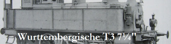
designed as branch line loco derived from a Prussian Class T3 of the year 1882. So no high tech compensation system or even steam brakes. All was hand operated but the set-up off the lever mechanism in the cab was done in such a way that the maximum brake power never exceeded the adhesion force of the loco; an early type of  anti-lock brake system (ABS) 


I first started with designing the brake system in Solidworks. These drawings provided the data for the CAM-system which in turn generated the CNC-code for my milling machine.


This was one of the first programs I made for my new milling machine but it took more than a year before it came to production...........as always several other parts of the loco were made first and took more time than originally planned.


The production of one evening.


For bending the brake hangers a simple tool was made. A locating pin made sure that all the bends were at the same location.


The bending was done in one go; these photos show the 2 mm offset


The vice, complete closed.


Two hangers together. The locating pin in the bending tool is visible. The two parts are silvered soldered. cleaning up (by hand) after soldering took more time than making the parts.


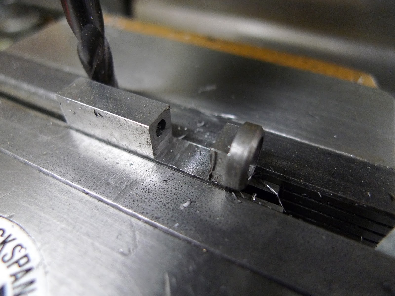
The brake blocks were made from mild steel. With the boring head in the milling machine set to the wheel radius, and set-up under an angle of 3 degrees (wheel profile), the first shape is cut.


The finished wheel profile against a fixture, so that the holes for fixing the blocks in the hangers could be drilled.


After milling a recess the next step is made in the fabrication of the four blocks. Although the loco has 6 wheels only the last four are braked.


The boring head is set to a different radius so the shape of the block could be cut.


This was done at both sides of the material.


Half way there.


The CNC milling machine is used again to cut the outer profile of the brake blocks.


The last millimetre was cut by hand. This method made it possible to get a sturdy set up in the milling machine and use the drilled holes as an easy 'zero-point' for the CNC program.


The complete blocks and hangers on a real brake shoe of a German steam locomotive (Baureihe 23).


 The four blocks with the locking pin. On the right you see the first test part of the CNC-program milled in plastic. This was done when my CNC-milling machine was just finished in February 2013.


The hanger brackets were milled from a solid piece of mild steel. 


For easy set up in the vice two hangers are made side by side. 


The radius was made the old fashion way: with filing buttons which were used as a guide for filing the radius by hand. This could be done by CNC, but because there are only two parts it's quicker by hand.


A test fitting for the front hangers.


For the brake lever in the cab I had only a few photos I've made in the museum to work from. It consist a toothed ratchet system. The ratchet was cut with a dove tail cutter and dividing head.


                                  Brake on position.                                                           Brake off position.

A 30mm square tube was cut in half and silver soldered to a base plate. The lever with contra weight will operate the pull rod.


The ratchet system with catch pawl


The complete set up in the rear of the cab (which is dismantled).


The brake hangers in position on the chassis.


The cross pull rods were build up from two end pieces and a strip in the middle.


In these holes the pulling rods will be mounted. There are no compensation levers, only simple threaded pulling rods


A completed cross rod.


The last part; the brake shaft which connects the pulling rods with the cab brake lever.


The locomotive on 23 March 2014, at our annual model engineering exhibition at Loon op Zand: 
with the brakes fully applied!

Sunday 5 January 2014

Fire door

The fire door is a typical small round door, found on many branch line locomotives of that time. With a stainless steel plate the complete fire door assembly will be screwed to the back head of the boiler. The door opening is 45 mm.


The door is made of plain carbon steel and was turned on the lathe with several  radiused tools to get it in this shape. The door on the original locomotive was casted from cast iron. The four small holes in the door are for secondary air over the fire.

The stainless steel base plate was turned in the 4 jaw chuck and a small recess on the back of it, was made so it can be snug fit to the boiler fire hole.

In the milled reces on the door, a small hinge was inserted and fixed with the three M2 hexagon bolts

The other part of the hinge was made from rectangular bar. This was set up in a four jaw chuck to get a small cup at the top side of the hinge. With the aid of a dial indicator the block was centred.
  This cup on top will have a small groove that will act as a catch for the door handle.


The surplus of material was milled away.

The recess for the hinge was milled with a 6mm endmill

The almost finished part of the hinge; only fixing holes to be drilled and a groove in the cup for the door handle


 The set up for the door. A small screw can be seen at the back of the door hinge; this will lock the hinge pin.

The door handle is filled from 2 mm steel plate. On top of the hinge pin a bush is taking up the handle. A small 2 mm reces in the cup will keep the door  locked  in position.

The door temporary fixed on the boiler

A 1 mm stainless steel fire door back plate was spun in the lathe.

For the spinning of the plate a tool was made. This is nothing more than an old ball bearing pressed on a bar, which is hold in the tool holder.

Two former blocks hold the plate in place while spinning. This spinning is done at approx. 250 rpm

The spon plate.

Fixed on the door. The secondary air will first hit the hot plate, before entering the firebox.

The finished door is burned in old motor oil. This will leave a black coating on the door which is fire resistant.

 Only the door handle grip is polished. The wide fire hole makes the grate visible; even when looking from above. Checking on the fire while driving the loco should be a bit easier this way.

Thursday 2 January 2014

Fire grate


The grate and ashpan in the Solidworks drawing. The grate is hinged and can swing away when the drop pin is pulled out. The ashpan is completely open at the bottom. So there is plenty of air to keep the small coal fire burning and there will be no build-up of ashes; good for a full day of driving. If needed a separate plate can be mounted on the underside of the ashpan. I've closed the bottom of my 5" 14xx class locomotive; but this wasn't a success due to the build up of ashes which deprived the fire of oxygen in the end. 


The fire grate of the T3 is only 150 x 100 mm and is a relatively simple affair. The bars are cut from stainless steel 3mm plate (316L). This takes an afternoon to saw these from a plate by hand.


On the shaping machine the strips of steel were shaped to bars of 12mm height.


In the milling machine all the holes were spotted with a centre drill.


 With the aid of a simple jig, which was made on the shaping machine, the bars were V-shaped milled. Only at the position of the bushes the bar was left parallel.

A test setup with the spacer bushes in place, they are 4 mm wide.

 The complete grate, viewed from the under side. The lugs in front is for the hinge pin, with which the grate is held in the boiler. The lugs on the left are for support of the so called dumping pin. If this pin is removed, the grate will swing down and the fire will be consequently dropped

 The ashpan is build up from 1 mm stainless steel plate, which was left over from the kitchen renovation. 
With a few M2 screws the parts are firmly bolted together.


The complete ashpan and fire grate read for assembly to the boiler. In the front there is a double plate; I saw this on real locomotives, so the radiation heat is kept away from the axle.


The grate 'in working order'  at DBC-H Schackendorf  30 June 2018.