The boiler construction.
( a long overdue update for this blog)
( a long overdue update for this blog)
The steam boiler for my Württembergische T3 locomotive is a standard coal fired copper boiler, designed for a steam pressure of 6 Bar (approx. 90 Psi) . All the
flanged boiler plates are silver soldered and the stays are of the screwed and
caulked type.
This
design is used the past decades in the
model engineering world with success, and when well-made it will give you an easy to maintain boiler that will last
for a long time.
Boilermaking
isn’t as difficult as it looks, but it's different than machine work and most
tools used are used by hand. In both cases planning ahead and making the
individual parts will take up most of the time.

I started with the boiler parts in 2010. The drawing of the boiler was made in Solidworks and made according to suit the Dutch boiler design rules. (These are derived of British, Belgian and German model locomotives regulations and the European PED)


The boiler barrel has a diameter of
133 mm, the total boiler is 630 mm long, the firegrate measures 105 mm wide x 155 mm long. There are 16 fire tubes; 430 mm long and with a diameter of 15 x 13 mm. Two water gauges are fitted and a Stroudley regulator will supply the steam to the cylinders. A Ramsbottom safety valve is set to a working pressure of 6 Bar. Water supply for the boiler will be done by a live steam injector, an axle pump and steam pump.
The total boiler weighs approx. 19 kilogram and holds 6 liters of water.
The drawing of the complete locomotive (including boiler) can be downloaded as Solidworks 2014 file. Kick here for Mediafire or here for Grabcad download site.
The total boiler weighs approx. 19 kilogram and holds 6 liters of water.
The drawing of the complete locomotive (including boiler) can be downloaded as Solidworks 2014 file. Kick here for Mediafire or here for Grabcad download site.

Stress analyse and calculations were done on paper and with a Finite Element Method (FEM) in Solidworks .
-Displacement-Displacement1.jpg)
A static displacement calculation shows (842 times enlarged) the deformation at boiler pressure of 6 bars.
The fabrication was very simular to the boiler I've made for my 5" gauge GWR 14xx loco. Only this boiler is a bit bigger. But not that much; a 5" gauge German BR64 has about the same dimensions as this 7¼" gauge loco.


Former plates were made of 25 mm thick aluminium on a professional CNC DMU 50 milling machine.
The copper plates are 3 mm thick.
For 7 ¼" gauge this will be a rather small boiler.

The plates in a temporary fire hearth for annealing. Heating up was done by a large Sievert propane torch. The annealing was repeated several times, to get the final shape. The annealing itself is nothing more than heating the copper until it reaches a bright red color and let it cool down again. This softens the copper, so it won’t ‘crack’ during the forming process.


The inner firebox front plate during heating.

Due to the deformation the copper will get hard again; therefore several heatings are needed.

Especially in the corners (where there is a lot of material displacement) work hardening will occur more quickly and reheating is necessary.

The firebox plates are getting into shape.


Almost there; one final heating and hammering is needed to complete this plate.

The flanges were made to length, after they were formed. In this case the blanks can be roughly cut to shape, when starting with fabrication of the plates.

Filing to the final dimension (an overlap of 8 mm of the flanges)

The inner and outer firebox plates. In this position the outer- and inner-firebox will be located once the boiler is finished. The water space on the sides of the firebox will be 11 mm and in the front and back will be 15 mm.

The throatplate is also made of 3 mm thick copper plate.

A special formerplate was needed for making the outward flange. With a wooden tool the first bend was made.

The first stage of the throatplate.

The finished plate after removing the excess of material.

The outer firebox shell (which was annealed first) was bend over the boiler barrel.

Final shaping of the firebox shell between the bending rolls.

A test fitting of the outer boiler.

The drilling and boring of the holes for the fire tubes was done on my milling machine. With the aid of the Digital Read Out is easy to locate the holes in the correct position, as determined with the CAD software.

The tubebank during test fitting.

The smokebox tubeplate. Boring 15 mm holes for the fire tubes. The real loco had no super-heater, so it will be omitted in the model as well.

A rear view through the boiler.

A test set-up of the tube bank. The holes are all a little oversized and not, as stated in most of the available construction notes in the ME press, reamed to a close fit. This would be incorrect for soldering, as the tubes will expand during the process and than there would be no gap for the silver solder to penetrate. To prevent leaks around tubes, a rough surfaced hole and a little over dimension of the hole are ideal, so that solder will always be able to get in the joints. This was done by using a rough round file in the bored holes.


Set-up for soldering the firebox tube plate.


As can be seen on these pictures, there is a good penetration of silver through the joints.

For bending the inner firebox shell a small bending tool was made. Although very basic, it did the job wonderful.

Checking the gaps
On my 14xx 0-4-2 loco the firehole is conical shaped.
Because I experienced on my 3.5" tank locomotive that your view on the fire is limited, once you are in the driving position behind the locomotive. A conical shaped firehole gives a far better view on the small firebox and it gives also the opportunity to control the fire. For groundlevel driving this is a welcome extra.
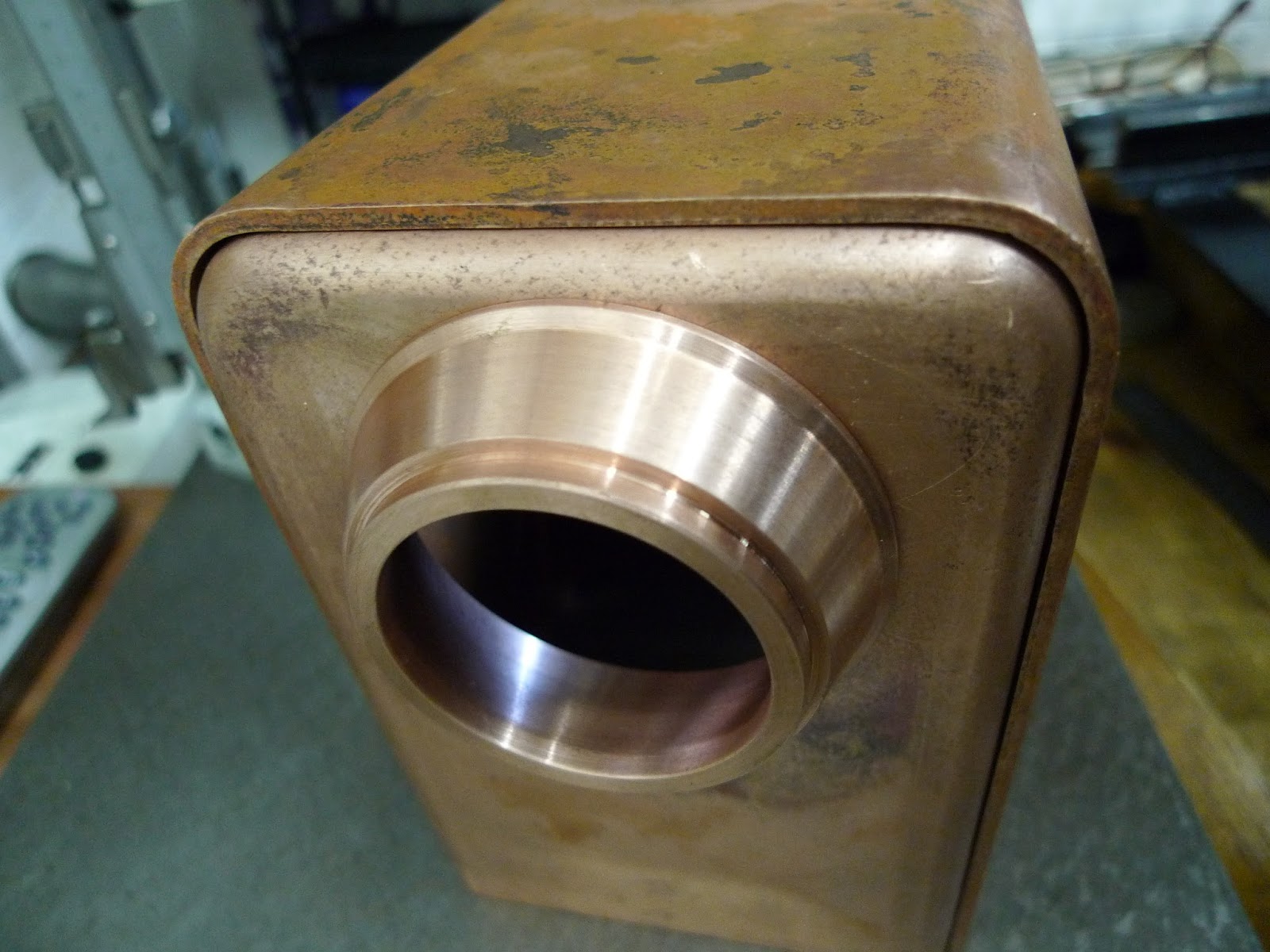
For this purpose a special conical ring was turned from copper bar. On the outside of the boiler backhead it is only 46 mm in diameter, but on the inside it is almost 62 mm in diameter.

A good sized firehole

Making the holes in the backhead plate for the boiler fittings.

Boring the holes for the safety valve and turret bushes in the outer shell.

Girder roof stays are used on the crown of the firebox to give the strength.

To obtain a good fit in the boiler, a special former block was made for the production of these girders.

This former block was adapted for usage in the plate folding machine.
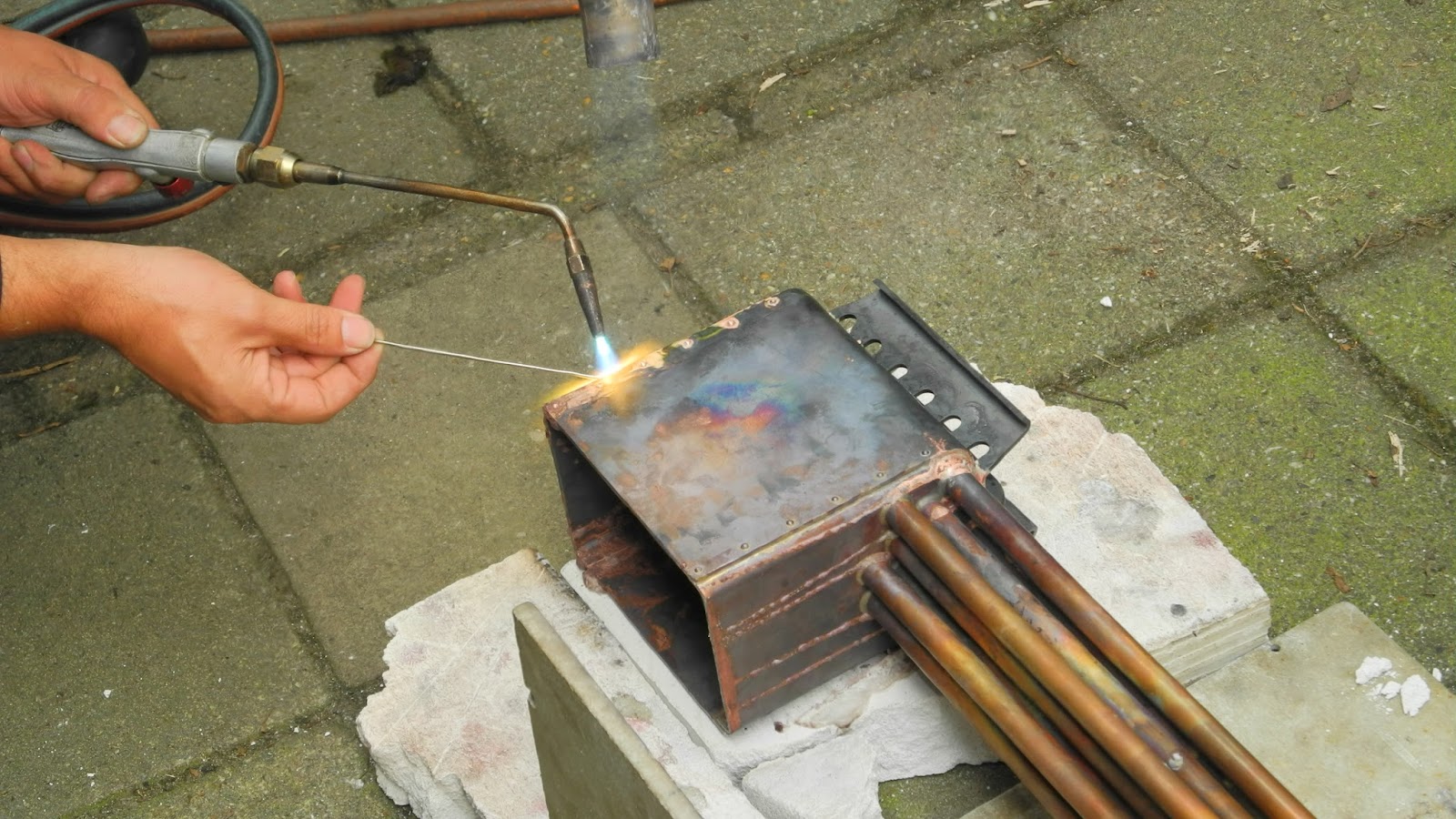
The first soldering operation on the inner firebox.
Soldering was mostly done with a Sievert propane burner and a oxy-fuel burner. The summer allowed me to work outside the workshop. With such a large boiler it is almost impossible to solder inside the workshop. The small parts I did solder in the workshop, rose the temperature very quickly up to 45° C.

When the parts were sufficient cooled down after soldering they were pickled in acid. The tank I used, normally functions as our chemical waste container.
After about ten minutes in the acid, the copper comes out of the pickling tank with a nice pink clean surface. This removes the oxides and brazing flux residue from the copper in a fast and efficient way and also prepares the copper for the next stage of soldering.

Aligning the boiler barrel and outer firebox wrapper.


The photo shows the outer boiler just after it was soldered, with the flux still on it. Where there isn't any flux, the copper will turn black after cooling down. Pickling the boiler in acid will remove this black oxidation layer.


The crown stays in this boiler are of the so called ‘girder stays’ type This type of stay is relatively easy to fit and solder in the boiler and is easy to check if the stays did have a good fillet if silver solder all around. The water circulation on top of the firebox should be good with the holes provided.

A test fitting on the frames and between the side tanks and cab.

The foundation ring consists of four separate pieces of copper bar, that are riveted and soldered in position.

The boiler is almost ready for the last soldering operation.

A layout for the firebox stays. It is vitally important that all flat plates in boiler are adequatley supported and strengthenend by means of stays. Firebox side stays are ftted to prevent the inner and outer plates bulging and collapsing due to the stresses induced by the steam pressure.

The stays are of the screwed and caulked type. At a spacing of 20 mm, M4 holes were drilled and tapped, to take up the 4mm copper threaded stays. I used this method on my other loco's; my 3½" loco is in service for almost 30 years.

Every stay was individually made and fitted. This takes up several evenings to complete the job of staying the entire boiler.

At a steam-up in Breda one of our club members found out that this method is not only easy during manufacturing, but is also a very good safety measure if the water level should drop to low. He had trouble with his locomotive and the water level fell dangerously low. The soft solder of the top row of the stays melted and water and steam extinguished the fire before any real harm was done. He dismantled the locomotive at home, cleaned the boiler, resoldered the stays and was back in steam the following event.

Drilling the holes in the throat plate calls for an extended drill. Therefore the 3.4 mm drill was glued with Loctite in a 8 mm rod. Drilling this way went fine, although the long drill needed some guidance by hand.

Once the boiler was finished is was ready for hydraulic testing. I used a small water pump for that, which was connected via a copper pipe to one of the bushes. All the others were blanked off, except for the dome top bush, to which a pressure gauge was attached.
The boiler was completely filled with water and pumping began. Within a few strokes of the pump the pressure began to rise.

The testing pressure of 12 Bar (1.2 Mpa or 174 PSI) was reached. This pressure was kept for 30 minutes.
I contacted the boiler inspector and made an appointment for the official test.
On the 9th of November 2012 the boiler was approved by the Inspector. However a boiler certificate will be issued after the steam test.

On the 9th of November 2012 the boiler was approved by the Inspector. However a boiler certificate will be issued after the steam test.


