Welcome

Live steam model on 7¼" gauge of the Württembergische T3 no 924

Welcome to this blog. It will inform you about the progress of designing and building live steam model locomotives. The blog contains the description of a model Würrtembergische T3 on 7¼" gauge (built between 2006 and 2017), the wagons for this loco (built between 2018 and 2022)  and a 5" gauge model of a Great Eastern Railway Y14 class loco (started in 2020)

On the left you'll find the index where you can browse through the different articles and on the right you'll find all the extra's. On the top tabs you'll find a brief description of my other locos.


Click for the direct link to start of construction series below 
T3 7¼" steam locomotive 
 
Enjoy this site. Erik-Jan Stroetinga. The Netherlands. Europe.


Monday 2 October 2017

2017 Le Petit Train a Vapeur de Forest, Bruxelles

The first steam outing with the new loco at PTVF

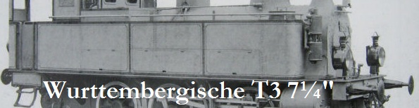
Loco as it was still under construction in 2014. 

Three years later in October 2017 we took the finished locomotive for the first steaming to the magnificent track of the Model Engineering Society of  Le Petit Train a Vapeur de Forest in Brussels.  Their last weekend of the season (end of September) is always a nice happening, with a warm welcome and a very interesting track layout, with different loops, crossings and some steep gradients. The different routes are set by numerous points and signals.
We had a great weekend and the locomotive performed very well. 
(Don't forget to see the video at the end of this page)


A set of wagons was kindly lent to us to play with this weekend. 


Out of the car and onto the track in front of the main buildings of the ME society. 


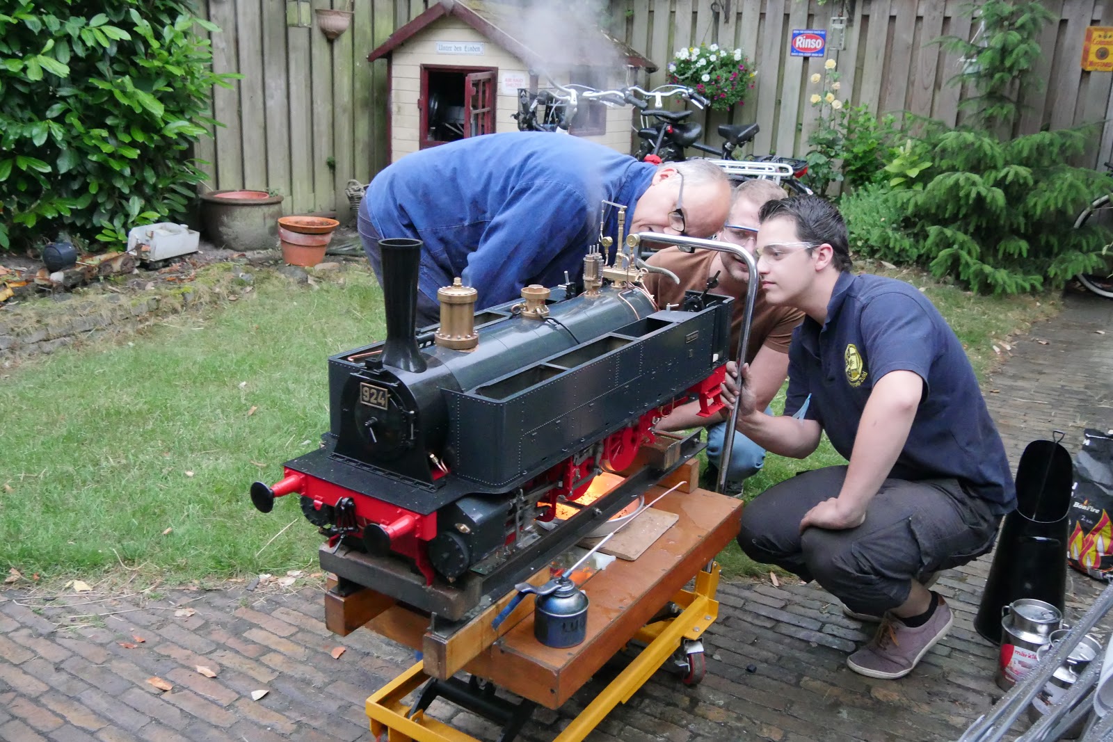
In the loco yard, preparing for the first day of driving. 

On the steaming bay the boiler and tanks were filled and the fire was lit.


Driving onto the turntable.


The main station.


A stop for the signal, waiting for other trains on the main line.


Getting to know the performance of the enige. 

Although the loco is not fully completed yet, Martin is satisfied with it.


Robert (the owner of the wagons) taking the train for a lap around the track.


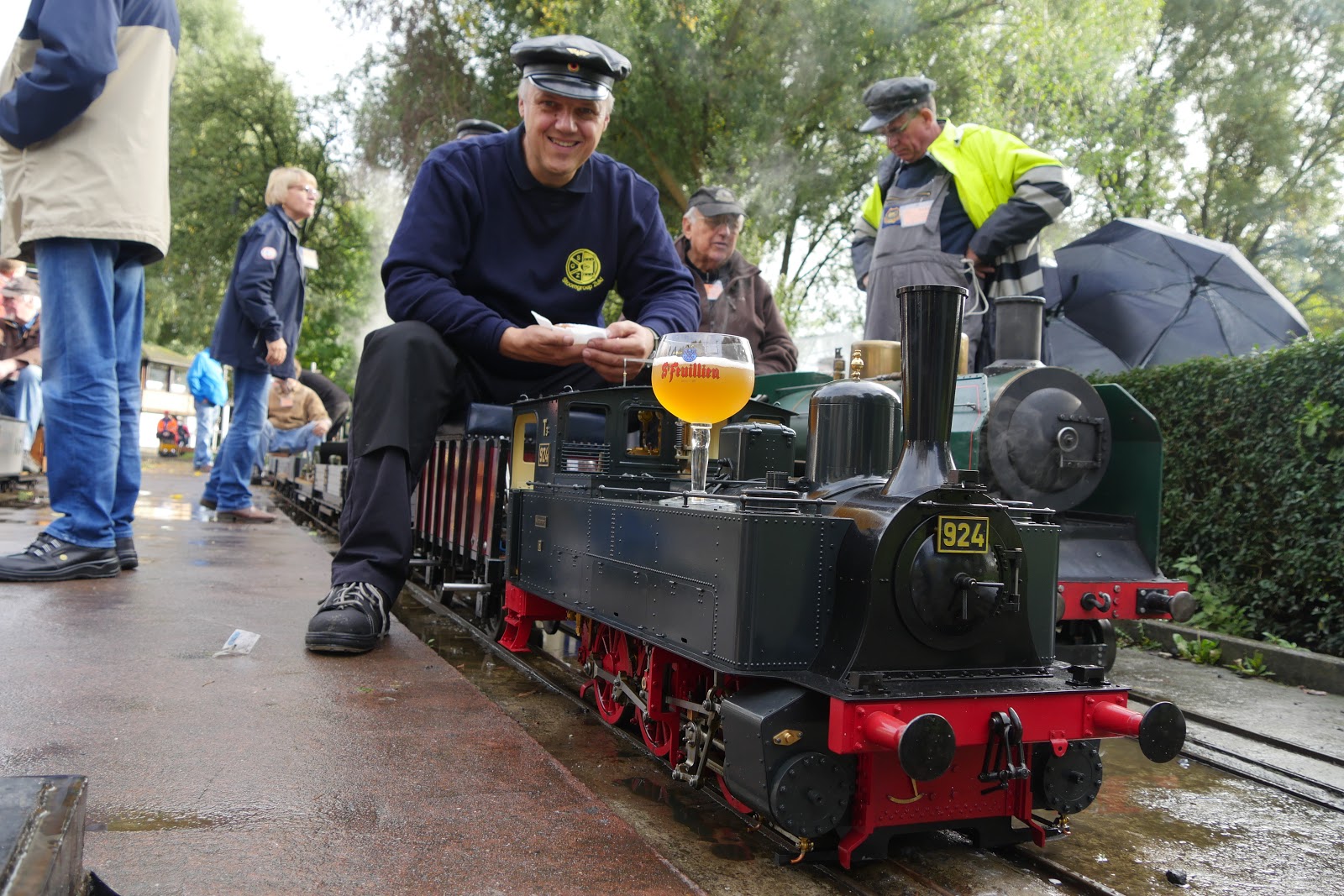
Nice size of loco.............


After 8 hours nonstop in steam, the last lap of the day.

To the ash pit to drop the fire


and blowing down the boiler.


Cleaning the engine after a weekend of steaming.

 PTVF has an excellent engine shed to do this, where the loco is at a comfortable height for cleaning the moving parts and frames.


We would like to thank the PTVF for their hospitality and a great weekend! 


A short video of the locomotive in steam at PTVF

Monday 18 September 2017

Maiden Trip Württembergische T3

On Saturday 16 september the locomotive was out of the workshop and loaded into the car, for her maiden trip at our club track at Breda  (www.stoomgroepzuid.nl) . After almost 11 years of designing and building the loco was taken to the track for the first time.


On the hydraulic lift, ready to load in the car. 


At the track the loco was prepared for steaming. 


After the boiler was filled with water, the fire was lit and the new electric blower put to work.  
The filling plug (hidden under the sand dome), makes is much more comfortable to fill the boiler. On my other 3½" and 5" gauge locomotives this is done with the hand pump, what makes it a much more labourers job.


It takes about 25 minutes to get the boiler to working pressure (90 psi or 6 bar) and then about 5,5 liter of water is heated, during this time the loco could be greased.  There are a lot of points to oil and because this is the first time the loco will run under its own steam, we used plenty of oil. 


Once the boiler pressure was reached and the safety valves started to lift, the locomotive was driven on the turning table and main track.


After a final check Martin took the loco for her first lap ever under her own steam. We had to use our 5" gauge driving trolley. The wagons for this loco have yet to be build.


Everything seemed to work as is should and it got the ok from the driver.


The first two laps the loco was a bit 'stiff'' and did not run easily.  This was due to the heavy steam oil, still in the cylinders from the last test in the garden. After that test, we flooded the cylinders with oil to prevent rust to set in. This was more than a month ago and this oil took some time to get 'fluid' again. 


After that the loco ran very smoothly and was able to run on a steam chest pressure of only a 0.5 bar.


After  a few more laps and this first initial test,  the boiler was blow down and the loco was left to cool down.

Ready for the next run, the next day at our open day at Stoomgroep Zuid.  We used a lighter oil for injecting into the cylinders after the run, to prevent corrosion.  This is done by feeding oil through the exhaust pipe and then pushing the engine over the rails. The reverser is then set in the opposite direction in which the loco is moved. This way the oil is sucked into the steam chest and cylinders. When oil, instead of water, is coming out of the cylinder draincocks you know that there is enough oil in the steam engines.   


On Sunday 17 september we had our annual open day at our model engineer society Stoomgroep Zuid (Breda the Netherlands)
I was able to borrow a real 7¼" driving truck from one of our club members for this event and the loco was put into service almost the whole day.

As Bob Symes stated in his television program "Model World" of the '70ties:  "it's nice to drive your own loco" .  How right he was!


A busy day at our track.


Martin explained the function of the boiler fittings, reverser and the general working of the locomotive.

The loco was kept in steam for the most part of the day; the lovely weather helped of course.


The boiler is easy to fire and seems (we only had a light load behind the loco) keeps up steam pressure without any problem. 


 A lap at our club track.

Making a driving truck,  the steam pump and finishing the details as lamps etc. are the next step.

Saturday 24 June 2017

First steam test


In the evening of 24th of June, we've made the first steam test.  After almost eleven years of designing and building the first fire was lit in the firebox and the locomotive came alive on the test stand.


A simple match was all that was needed to bring her to live.


With charcoal and some coal (to temper the fire, because the newly made electric blower is a bit strong) a fire was build.


For the approx 5,5 liter of water, 25 minutes was needed to get the boiler to steam.


The motion oiled and ready for the test.  The engine was jacked up on wooden blocks. 


Moving under its own steam.


A nice glow of burning coal in the firebox. 


Watching the needle of the pressure gauge, the water gauges and the fire closely.  For this test the top of the tanks, top of coal bunker and cab is not yet mounted. This way is was easy to inspect all the boiler fittings and valves.  


The whistle sounded ok. 


After a half hour in steam the fire was dropped and the boiler blown down. 

So far most things (water pump, injector, water gauges, check valves, lubricator, "Everlasting" blowdown valves) seems to work.
The regulator (some leakage) and the dropping of the fire grate (not dropping easy)  need some attention. 

Tuesday 13 June 2017

Boiler cladding part 2


Progress has been made on the assembly of the locomotive. The tanks are mounted on the running boards and the lubricator is connected to the cylinders.


The connecting pipes for the axle driven water pump have been also made. With an extra bend, so it can avoid the front axle, it will connect the filter outlet from the tanks with the suction part of the pump.


Oil pipes were also made for the eccentric and the pump ram. The lubrication of these parts is by drip feed from a second oil tank that is mounted on the running board.  A thick piece of felt is inserted in this tank, that in effect is blocking the exit to the oil pipe. This way there is a 'controlled' feed rate. 


A view from the underside of the locomotive front end. The connections to the water pump are visible; and they are reachable with a wrench, without the further dismantling of other parts.  I hope this way dismantling the pump for maintenance is easier than on my other locos. 


I decided to use 3mm thick cork sheet for cladding the boiler. This material has a good insulation factor, is relatively cheap (I've paid €29, --  for a roll of 5 meters ), easy to work with and can withstand moisture. 


I was able to fix three layers on the boiler barrel.


Cutting was done on a piece of hardboard, with a sharp pocket knife. 


With some tape the individual pieces were temporarily held in place;  the brass lagging sheet will hold it in position afterwards.


On the firebox shell a recess was cut for the boiler stays with a small hollow punch.


The boiler fully lagged, ready for taking the 1 mm brass lagging sheets. See therefore this earlier blog.


The completed boiler.


The final assembly of the water gauges could now be done.  Again I used the blue silicone sealant (Loctite 5926)  for the flanges of the gauge. 


The gauge glass itself is sealed with a silicone ring, which was cut from a piece of tube with a scalpel. 


The easiest way is to do this is on the lathe, when the tube is slit over a piece of brass (or wood) and the scalpel mounted in a tool holder.


A ring of 2mm height is placed on the bottom nut, a ring of  2,5mm height was used on the top halve. This was done because I had little space on the top part to cut more screw thread.  Only finger pressure is used to tighten the nuts.
The holes in the bottom and top parts and the nuts are slightly larger (6,2mm) than the glass diameter (6,0mm).  This will allow for the difference of expansion of the glass and brass. The glass should never touch the brass parts, otherwise the danger exists that due to tension the glass will crack once the boiler is on working temperature   (approx. 160 degrees Celsius by 6 bar working pressure)


A black and white striped plate is situated behind the gauge glass.  This makes it easy to see the water level in the gauge glass.  Due to the difference in refractive index  the cross stripes at an angle, will appear horizontal there were there is water in the glass tube. On the photo the plates are taped on a piece of metal, so I could hold them for paint spraying.


The backhead of the boiler. The water gauges in position, with their blowdown cocks and pipes.
The "Everlasting" blowdown boiler valves are also mounted on the boiler. 


Extension pipes (6x4 mm copper) are screwed on the blowdown valves. They extend to the rear of the loco, just below the bufferbeam.


The boiler sitting in the frames. 


Also a first concept of the drawing of the steam pump has been made.